Electric trolling motor / controller diagram / need help

fredwanagon

Recruit
Joined
Jun 18, 2007
Messages
4
I have a Johnson 1974/1975 electric trolling motor. The speed controller was stock full throtle.

I got onto internet to find electrical diagram to buil anew circuit since the old one was all glued in the cassing. I ahd to destroy it in order to get access to the vertical post to run new wires.

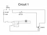
I tried circuit 1 and it work for about 10 sec until the motor stopped. The transistor was somewhere between very hot and hot.

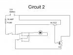
Can someone tell me the differences between circuit 1 and circuit 2 in attachment?

I want to try circuit 2 but I would like to understand the voltage and current variation all around the circuit before.

Thanks for your help.

Fred
 

Attachments

  • circuit1.JPG
    circuit1.JPG
    32.3 KB · Views: 0
  • circuit2.JPG
    circuit2.JPG
    32.4 KB · Views: 0

Silvertip

Supreme Mariner
Joined
Sep 22, 2003
Messages
28,771
Re: Electric trolling motor / controller diagram / need help

The main difference in the two diagrams is just the method of biasing the transistor. The transistor by the way is very under-rated for this type of service. It has a power dissapation rate of 150 Watts and a maximum collector current of 12A. The motor obviously draws less than 30 amps since the 30A fuse holds up. At 20A it has to handle 252W so it is no wonder it is getting hot. These motor controllers were not battery friendly as they drew the same current regardless of speed setting. They just wasted energy by turning it to heat. You would get the same effect by using a huge rheostat and simply inserting it in the +12V lead. The rheostat turns excess energy into heat. Am I correct in assuming this diagram was shown as an easy way to control an electric motor -- but they didn't specificy "trolling motor" or what the "current capacity" of the circuit??
 

fredwanagon

Recruit
Joined
Jun 18, 2007
Messages
4
Re: Electric trolling motor / controller diagram / need help

I'm really open to suggestions to improve the efficiency of my controller. If someone has a diagram and part numbers to suggest, I would try it unless it cost too much.

Thanks for the reply
 

Silvertip

Supreme Mariner
Joined
Sep 22, 2003
Messages
28,771
Re: Electric trolling motor / controller diagram / need help

Motors like the MinnKota Power Drive for example use a pulse technology that makes these newer motors much more battery efficient. Wide open all trolling motors use the same power regardless of technology so there is no improvement there. But with older motors, either big wire wound resistors (speed coils) or a circuit like you are trying to build were used. They are inefficient because the total current draw is the same whether you are running wide open or not. To build a pulse type of circuit is far too complex and they include integrated circuits that you probably can't get on the open market anyway. Don't beat yourself up trying to salvage this old motor. You'll spend more money on it than its worth. Heat is the enemy with these old motors. It amounts to wasted energy and there simply no way to get around it. There are some commercial motor speed controls but they will be expensive. Check on E-bay for a motor like you have. Even if its dead, the controller might be salvaged.
 
Top