Always refer back to the wiring diagram it will help to understand what should happen
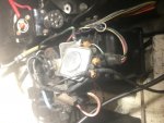
J and E are purple and strange. They are tied together in continuity but have no continuity at plug? They are both in same arm off harness but aren't connected physically. About 12" apart they branch out of the run. They are connected when I attach meter to each one. So it's a loop? But not to plug?
Key here is the wire is purple, so this is 12V when key is turned ON. You want 12V to power the coil and choke. So this should go between carb and coil +, this is probably the resistance wire for the coil run connection.
I is officially purple. It goes to pin #5 so it's choke. There is another wire that was added to it and it proceeds to positive coil in conjunction with purple/yellow that comes out of end of harness. They both were attached to the old coil on the positive. So not really sure what they are?
It should go to the choke. The purple/yellow should go to the slave and is used to give the coil full 12V during the start cycle.
L is pin#2 it is 2 tan wires together. So negative coil
If it comes actually from pin 2 then it should be Gray. Being there are two wires and you have continuity between them back to pin 2, this would tell me they are actually Gray. If this is correct then one would go to Negative coil and the other would go to the shift interrupter.
If it is Tan then it should come from pin 3 and go to the water temp sender
F is tan as well it's also negative coil
Does it go to a pin ?
N brown goes to pin 10 so it's trim sender. Manual shows it going to a terminal block first then sender
Agree IF there is a terminal block, otherwise it can connect straight to sender wire with a bonnet connector
I'm not quite there yet want to get wiring done first. But may as well ask now. Regarding sealants
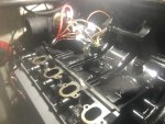
What do you guys use on the intake? I was thinking is use the permatex aviation?
And exhaust manifold, nothing?
Carb probably nothing?
Valve cover gasket?
I use nothing on gaskets except on corners on V8 intakes. Since this is a 470 I'll let the 470 guys answer this one


") .
.