Help diagnosing no start

bcontento

Seaman
Joined
Jul 10, 2017
Messages
50
I have an older Evinrude that I've been working on. A Couple of days ago, turn the key and it would start and run. Now I turn the key and get nothing. No clicking in the solenoid.

The solenoid bench tests fine. With it installed I do get 12 volts on the signal post when I turn the key but no clicking. Apply 12 volt directly to the starter and it spins.

I thought maybe a bad neutral safety switch but I thought it was already bypassed by the previous owner.

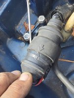
These four connections were electrical taped individually and not in use I believe when it was starting. Not sure where they go or what they belong to. I know that if I turn the key off the motor does not start. I have to starve it to shut it down.
1000017848.jpg
 

Crosbyman

Vice Admiral
Joined
Nov 5, 2006
Messages
5,678
first thing is to state the HP... model-year number

second is look for any fuse if provided in the diagram which could... be found here

no click on the solenoid and 12v is present on the control post when key is at start.... can be
bad solenoid
, bad 12v( highly resistive due to oxidized connections somewhere... )
bad solenoid grounding ...
bad ground on the engine due to bad battery cable or crimps or connection to the the engine frame.
 
Last edited:

bcontento

Seaman
Joined
Jul 10, 2017
Messages
50
first thing is to state the HP... model-year number

second is look for any fuse if provided in the diagram which could... be found here

no click on the solenoid and 12v is present on the control post when key is at start.... can be
bad solenoid
, bad 12v( highly resistive due to oxidized connections somewhere... )
bad solenoid grounding ...
bad ground on the engine due to bad battery cable or crimps or connection to the the engine frame.
When I bench tested it I did get the solenoid to engage and got 12 volts on the starter side so I'm thinking it's not a bad solenoid. If I'm getting different results with it installed I could see possibly bad ground.

If I touch my multimeter negative probe to the I terminal on the solenoid and positive on the battery I should get 12 volts correct? I only get about 3v. I ran a jumper from the I terminal to known good ground and if I do the same test now I get 12 volts but still nothing when I turn the key.

Took the solenoid back out to bench test it again to make sure. I have a hot from a good battery to the positive side. I have a hot from a good battery to the s post I have the positive side of my multimeter connected to the starter post. When I ground the I post, solenoid closes and I get 12 volts on the multimeter.

I put the solenoid back in but only wired it one piece at a time to test it further. Hot from the battery and hot to the starter. I connected the I to the known good ground and when I connected the s directly to the battery terminal the solenoid fires and the starter spins. I reconnected the ignition wire to the s terminal and left everything the same and get nothing when I turn the key.

FYI I might have misspoke or screwed my tests up when I said I got 12 volt at the s when I turn the key in the original post.

Does this now point to the starter switch? Could it be in the harness? Is there a diagram or a method for testing the harness?1000017849.jpg
 

Crosbyman

Vice Admiral
Joined
Nov 5, 2006
Messages
5,678
voltage readings are veny iffy at best if no amps flow to energize the solenoid ..... you can have12v all day and nothing happens without amps .

if a manually applied strong B+ makes the solenoid work ok the 12v from the key is resistive and by ohms law max volts and amps will drop at the high resistance point leaving a few volts at the solenoid. If you only see 3v then 9volts are being dropped at a bad joint or key contact !

that can be anything from batteryB+ to key .... from within the key or the control wire back to the solenoid so you must backtrack from the solenoid till you find the bad connection point or key contact. .check all crimps and wiggle things while holding the key is at START....... if you get a reaction you found the problem. .

I have had harness wires break just from flexing for 40 years ! suspect #1 bad connector ..try some wd40

check all pins inside that fat connector and indicate mdl- year of your engine !!!
 
Last edited:

bcontento

Seaman
Joined
Jul 10, 2017
Messages
50
voltage readings are veny iffy at best if no amps flow to energize the solenoid ..... you can have12v all day and nothing happens without amps .

if a manually applied strong B+ makes the solenoid work ok the 12v from the key is resistive and by ohms law max volts and amps will drop at the high resistance point leaving a few volts at the solenoid. If you only see 3v then 9volts are being dropped at a bad joint or key contact !

that can be anything from batteryB+ to key .... from within the key or the control wire back to the solenoid so you must backtrack from the solenoid till you find the bad connection point or key contact. .check all crimps and wiggle things while holding the key is at START....... if you get a reaction you found the problem. .

I have had harness wires break just from flexing for 40 years ! suspect #1 bad connector ..try some wd40

check all pins inside that fat connector and indicate mdl- year of your engine !!!
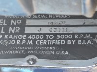
Sorry yes I forgot to post the motor info. It is a 72 40hp
1000017851.jpg

I have the ignition switch out and trying to test it for continuity but honestly can't find decent directions. My switch has terminals labeled battery s a and two m terminals on opposing sides. Battery is obvious. S I would assume is the starter circuit which would be sending signal to the s terminal on the solenoid correct? I would have thought that A was auxiliary. And I would have expected M to be magneto but why are there two? I don't have a terminal indicating it's for ground.

The wiring harness has five wires. Red white purple and two black (but neither of the black have any indicator stripe or anything to differentiate them. When I put my multimeter on the harness between red and purple I get 12 volts which means the purple is acting like a ground. Is it supposed to be? If I connect the red battery wire which has 12 volts directly to the White wire at the ignition key shouldn't that apply 12 volts to the s terminal on the solenoid and kick it over? It does not

With my multimeter connected up to the b and s terminals I do get continuity when I turn the key to start. With the key in the off position I get continuity between the two m terminals.

If I connect 12 volts to the battery terminal on the switch and my multimeter to the White wire on the s terminal I get 12 volts when I turn the switch on which should eliminate bad switch possibility.
 
Last edited:

Crosbyman

Vice Admiral
Joined
Nov 5, 2006
Messages
5,678
I have the ignition switch out and trying to test it for continuity but honestly can't find decent directions. My switch has terminals labeled battery s (STARTER CONTROL USUALLY VIA NEUTRAL INTERRUPT SWITCH OR DEVEICE) a ACCESSORY USUALLY PURPLE BASICALLY PROVIDES B+ WHEN KEY IS ON) and two m terminals on opposing sides. 2 M ARE USED TO KILL IGNITION ON MAGNETO TYPE IGNITION BY SHORTING OIL PRIMARIES BETWEEN THEMSELVES Battery is obvious. YES B+ POSSIBLY FROM A FUSE SOMEWHERE) S I would assume is the starter circuit which would be sending signal to the s terminal on the solenoid correct? YES BUT VIA AN INTERRUPT DEVICE TO PREVENT STARTING IN GEAR I would have thought that A was auxiliary. And I would have expected M to be magneto but why are there two? 2 M ARE USED TO KILL IGNITION ON MAGNETO TYPE IGNITION BY SHORTING OIL PRIMARIES BETWEEN THEMSELVES I don't have a terminal indicating it's for ground.

The wiring harness has five wires. Red B+ white purple out when key on and two black (but neither of the black have any indicator stripe or anything to differentiate them (NO). When I put my multimeter on the harness between red and purple I get 12 volts which means the purple is acting like a ground ( if key in ON B+12v will be sent over to A Purple) . Is it supposed to be? If I connect the red battery wire which has 12 volts directly to the White wire at the ignition key shouldn't that apply 12 volts to the s terminal on the solenoid and kick it over? It does not (White may be the solenoid control wire and if the solenoid does not react to B+ then the wire is open or a neutral interrupt device is openning the wire or the solenoid is bad or not grounded .. do ohms check along the way from key WHITE to solenoid WHITE )

With my multimeter connected up to the b and s terminals I do get continuity when I turn the key to start. With the key in the off position I get continuity between the two m terminals (NORMAL SINCE OFF KILLS THE MOTOR).

If I connect 12 volts to the battery terminal on the switch and my multimeter to the White wire on the s terminal I get 12 volts when I turn the switch on which should eliminate bad switch possibility.


I suggest you do some look up on typical switch control & wiring on oldies... B+ applied unfused could cook and smoke things you do not want !! the JOHNSON SERVICE manual has examples
 
Last edited:

bcontento

Seaman
Joined
Jul 10, 2017
Messages
50
Thank you again for the help!

If I turn the key on, I should be getting 12v at the S- white wire on the ignition switch, right? Whether or not it makes it's way to the solenoid it's a different story.

Did you see the photo of the plugs/wires that are disconnected? I was told they were left that way because the kill switch function was faulty. Are they ok to just not be in use a taped up? I'm wondering if they didn't fall off or pull apart in my messing with the motor but I have no idea what they are for.
 

Attachments

  • 20250506_120546.jpg
    20250506_120546.jpg
    2.5 MB · Views: 2

racerone

Supreme Mariner
Joined
Dec 28, 2013
Messages
38,481
There is a safety switch under the magneto plate.----Prevents cranking if throttle is open too far.----Just ONE white wire on this switch !------The loose wires pictured might belong on the " cut out switch " for 1 cylinder.----It stops spark on one cylinder should there be a high vacuum.----Sort this wiring out.
 

Crosbyman

Vice Admiral
Joined
Nov 5, 2006
Messages
5,678
If I turn the key on, I should be getting 12v at the S- white wire on the ignition switch, right?

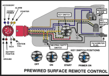
no... you only get 12v on the S when the key is at START ! at key ON only the A post (sometimes purple) has 12v see diagram above. for power transfer inside the key at various steps

killing the motor involves shorting the 2 M wires if the switch is a problem you can rig up any normally open push switch and kill the engine by pushing it
 

Attachments

  • omc  kill cct.PNG
    omc kill cct.PNG
    410.1 KB · Views: 1
Last edited:

bcontento

Seaman
Joined
Jul 10, 2017
Messages
50
If I turn the key on, I should be getting 12v at the S- white wire on the ignition switch, right?

no... you only get 12v on the S when the key is at START ! at key ON only the A post (sometimes purple) has 12v see diagram above. for power transfer inside the key at various steps
Sorry, that's what I meant. When I turn the key to start I should get 12 volts to the s post.
 

bcontento

Seaman
Joined
Jul 10, 2017
Messages
50
There is a safety switch under the magneto plate.----Prevents cranking if throttle is open too far.----Just ONE white wire on this switch !------The loose wires pictured might belong on the " cut out switch " for 1 cylinder.----It stops spark on one cylinder should there be a high vacuum.----Sort this wiring out.
Yes I believe that to be the case. Like I said the previous owner had bypassed some of that because of some problems. I'm just wondering if any of those disconnects what interfere with 12 volts getting to the solenoid. These have been disconnected and under electrical tape since I've had the motor and it's started and run BUT I don't know if they were taped together or taped apart!
 

Crosbyman

Vice Admiral
Joined
Nov 5, 2006
Messages
5,678
well wires usually go somewhere.... what is the consequence of leaving them open and taped up.

did you ever get the service manual downloaded. It has lots of info and diagrams you can look up. if you get engine & the solenoid working in neutral .... from the key you are all set ....... assuming key off kills the engine.
 

bcontento

Seaman
Joined
Jul 10, 2017
Messages
50
well wires usually go somewhere.... what is the consequence of leaving them open and taped up.

did you ever get the service manual downloaded. It has lots of info and diagrams you can look up. if you get engine & the solenoid working in neutral .... from the key you are all set ....... assuming key off kills the engine.
I did download the manual. Thanks.
So the clips that are disconnected, appear to be part ofg the "stop switch."
1746751507457.png

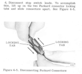
There is a detailed step by step method for testing ignition circuit that I'll walk through. There is also a detailed diagram of the big plug.

There is a fairly detailed wiring diagram that includes a "safety switch" and the "cutout switch." Is the safety switch the neutral safety switch? it doesn't really show the connectors to those switches, so I'm not sure if the two ring connectors that are just hanging belong to those. I do see in the illustration a spot where two wires connect (same location as the two I have). That is the vaccuum cut out switch, right? That just cuts out the ignition to one cylinder if needed, right? wouldn't keep ignition from firing.
1746753182014.png
 

Crosbyman

Vice Admiral
Joined
Nov 5, 2006
Messages
5,678
the vacum switch kills one coil as per description(high rpms) . on some motors the anti-start neutral control device can be mechanical or a simple mercury blob in a tube that shorts to ground only when attempts are made to start the engine in neutral. Out of neutral, the tube tilts and opens the needed ground path.... preventing the solenoid to be energized from the start key START B+.


if you remove the FW you will find a set of wires added on the condenser - coil connections on the points. those are the ignition kill wires routed under the mag plate to safety devices or wires.
 
Last edited:

racerone

Supreme Mariner
Joined
Dec 28, 2013
Messages
38,481
On this motor the " safety switch " prevents cranking if throttle is advanced too far.---Just under the magplate.-----ONE white wire only to it.-----Contact INSIDE this switch can be dirty.
 

bcontento

Seaman
Joined
Jul 10, 2017
Messages
50
On this motor the " safety switch " prevents cranking if throttle is advanced too far.---Just under the magplate.-----ONE white wire only to it.-----Contact INSIDE this switch can be dirty.
prevents "Cranking" meaning NO starter spin (like it interupts that voltage) or prevents the spark from firing?
 

racerone

Supreme Mariner
Joined
Dec 28, 2013
Messages
38,481
That switch prevents CRANKING ( turning of the starter ) with throttle open too far.----It does NOT prevent sparking.
 

bcontento

Seaman
Joined
Jul 10, 2017
Messages
50
GOT IT. Traced it all back to bad ground! Grounds that I've checked before and thought were solid. New ground wire and all is good.

Thanks everybody for your help!

Time to open a new post for the small manifold leak I just found 🤦
 
Top