120 Force No Spark

ScoLoc

Cadet
Joined
Aug 13, 2018
Messages
13
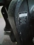
Pardon the long post. Just trying to be thorough. I am restoring an old boat that has been sitting at a friends for approx. 10 years. The outboard is a 120 HP Force by Mercury Marine. The serial number is 0E062161, which I understand is from 1990-1994. (no model no.) The motor was fogged before it was put away, then everything left to rot. I replaced the water pump impeller, cleaned up the fuel system etc., and it actually fired right up and idled sweetly on the earmuffs. Compression ~38 lbs in all cylinders. After patching the hole in the hull, replacing rotten wood and vinyl, etc. I poured in a 40-1 fuel mixture, dropped it in the lake for a trial run.

It was running absolutely great for the first half hour or so though I was taking it pretty easy. Alternating between idle and half throttle. Then it just suddenly died – turns out it lost spark to all 4 plugs and it hasn’t started since.

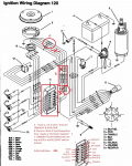
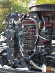
I'm new to the forumso can’t upload a picture yet, but my motor has the red stator, the single switchbox, and the 4 blue power packs. (CDM Modules?) and the auburn colored rectifier. It looks to me exactly like the one in the picture uploaded by ObiwanKenobi at https://forums.iboats.com/filedata/fetch?id=10340159. Except mine has what I believe to be the Red Stator Adapter strapped to the right of the swichbox where the white/green and green/ white wires from the stator connect through a box to blue wires which then terminate at the switchbox.

I have done what I could to troubleshoot according to several forum posts, but am out of ideas. I tried disconnecting the kill circuit by first disconnecting the black/yellow wire from the ignition switch, then from the switchbox. I was am confused however, as the experts consistently say to disconnect the black/yellow from the POWER PACKS, which I understand to be the blue coil units with the plug wire attached. But there is no black/yellow there on mine. The only black/yellow wire anywhere near goes straight down to a middle lug on the switchbox. And unpluging that does not restore spark.

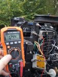
I checked (and replaced) the 20 AMP fuse above the rectifier. I unplugged the yellow wires to the rectifier. I unplugged the white/green and green/white wires below the stator, and tested with an ohm meter at 665 OHMS. The same wires cranked out approx 125.8 volts. (I don’t have a DVA but video taped the test and watched for the peak in slo mo.)

What did I miss. What else can I try?
 

pnwboat

Rear Admiral
Joined
Oct 8, 2007
Messages
4,251
It would appear that you've done the basic testing on the ignition components. It's looking like the SwitchBox itself may be bad.

Disconnecting the Black/Yellow wire at the SwitchBox disables the ignition Kill circuit, so you know that is not causing the "No Spark" condition.

The four blue power packs as you describe are actually the ignition coils. The ignition system on your motor does not have any separate CDM's or CD modules. The SwitchBox has the same function as the CDM's or CD modules on the other ignition systems..
 

jerryjerry05

Supreme Mariner
Joined
May 7, 2008
Messages
18,119
Post a pic of the lower unit, that way we can tell you the year.

The ignition system is Mercury.
I believe they used the Mercury stuff from 92-99
Outboardignitiondotcom has test procedures for your motor.
The DVA is a special meter for reading high voltage.
They sell an adaptor for a regular analog meter.
Or if your capable, you can make it?
  1. Disconnect the black/yellow kill wire AT THE PACK and retest. If the engine’s ignition fires now, the kill circuit has a fault-possibly the keys switch, harness or shift switch.
  2. Disconnect the yellow wires from the stator to the rectifier and retest. If the engine fires, replace the rectifier.
  3. Check the cranking RPM. A cranking speed less than 250-RPM will not allow the system to fire properly.
  4. Check the stator resistance and DVA output as given below:
Motors with Black Stator
WireRead ToResistanceDVA
Blue
Red
Blue/White
Red/White
3250-3650
75-90
180V or more
25V or more

Motors with Red Stator
WireRead ToResistanceDVA
White/GreenGreen/White500-700180V or more
Red Stator Adapter
WireRead ToResistanceDVA
BlueEngine GroundOpen180V or more
 

ScoLoc

Cadet
Joined
Aug 13, 2018
Messages
13
Thanks for the promp replies. Good to know the disconnecting ther kill wire at the switchbox is correct. I will try to post a pic of the tag on the lower unit.
 

Attachments

  • photo298747.jpg
    photo298747.jpg
    236.7 KB · Views: 7

ScoLoc

Cadet
Joined
Aug 13, 2018
Messages
13
Here's another thing. I noticed a spark between the rectifier/regulator and the bracked when I reattached. Looks like its shorted? Does this indicate a bad rectifier/regulator? Here's a picture:
 

Attachments

  • photo298748.jpg
    photo298748.jpg
    357.2 KB · Views: 14

Jiggz

Captain
Joined
Oct 23, 2009
Messages
3,909
There should be four wires connection on the rectifier. 2 yellows, 1 red and 1 gray. The two 2 yels are input from the stator and this is AC power. The red wire is positive output of the rectifier (negative output is through the body or case) and connects directly to the battery through the starter solenoid. And lastly, the gray wire is the signal wire for the tach to indicate engine rpm.

From the photo, you shouldn't be reading any voltage between ground and the body of the rectifier. Unless there is a direct short of the red wire internally to the case which is also the ground.

Your next diagnostic move is to disconnect the rectifier wholly from the system and try again. If still no sparks, then next move is to read the resistance of the stator (red and red/wht) and post your findings.
 

ScoLoc

Cadet
Joined
Aug 13, 2018
Messages
13
Thanks Jiggz. I disconnected the four wires and completely removed the rectifier. Again unplugged the black/yellow kill wire. Put the ignition key in run position and cranked the starter. Alas, still no spark.

I did not find a red and red/white wire to read stator resistance. The only wires I am seeing coming from under the stator area are the white/green green/white that I checked earlier at 665 ohms, and the cluster with the purple, white, black and white/black depicted in the below photo. Let me know if I am just not seeing something.

Meanwhile, I have now ordered a DVA adapter that is scheduled for delivery on Thursday. I will then complete the test procedure Jerry shared above. Will those results show me whether both the stator and trigger are functional, or just the stator?

Thanks all for your patience trying to walk me through this. My understanding of electric circuitry is lacking, and I really want to get this fixed. So your help is greatly appreciated.
 

Attachments

  • photo298784.jpg
    photo298784.jpg
    502.3 KB · Views: 12

Jiggz

Captain
Joined
Oct 23, 2009
Messages
3,909
Yes, the DVA will actually let you know if the stator is bad or not based on voltage output, i.e. 180+ vac.Based from the resistance reading it is a little bit at the low end, but that could just be the meter. If the stator voltage output is sat, then most likely the switchbox needs replacement. With a DVA, you can also check the input voltage to the switchbox and also its output voltage to the coils, 200~360 volts (output wire to ground).
 

Tassie 1

Chief Petty Officer
Joined
Apr 13, 2018
Messages
584
Umm,
l did read " ~ 38 lbs compression on all four..."
didn't l ?

Yep, l did.
 

jerryjerry05

Supreme Mariner
Joined
May 7, 2008
Messages
18,119
The comp 38 is more than likely 138
If it really is 38 on all 4 then the gauge is probably bad.
The good thing is they are ALL 4 the same.

The values I posted earlier are the wrong ones:( SORRY
They're for a 2cyl.
  1. Disconnect the black/yellow kill wires AT THE PACK and retest. If the engine’s ignition fires now, the kill circuit has a fault-possibly the keyswitch, harness or shift switch.
  2. Disconnect the yellow wires from the stator to the rectifier and retest. If the engine fires, replace the rectifier.
  3. Check the cranking RPM. A cranking speed less than 250-RPM will not allow the system to fire properly.
  4. Check the stator resistance and DVA output as given below:
Motors with Flex-plate Flywheel
WireRead ToResistanceDVA
Blue
Red
Blue/White
Red/White
5000-7000
125-155
180V or more
25V or more

Motors with Cast, Vented Flywheel
WireRead ToResistanceDVA
Blue
Red
Blue/White
Red/White
3250-3650
75-90
180V or more
25V or more

  1. Check the trigger resistance and DVA output as given below:
WireRead ToResistanceDVA
Purple wire (#1)
Brown wire (#3)
Purple wire (#1)
White wire (#2)
Brown wire (#3)
White/Black wire (#4)
White wire (#2)
Black/White wire (#4)
Engine GND
Engine GND
Engine GND
Engine GND
800-1400
800-1400
Open
Open
Open
Open
4V or more
4V or more
1V or more (a)
1V or more (a)
1V or more (a)
1V or more (a)
  1. This reading can be used to determine if a pack has a problem in the triggering circuit. For instance, if you have no fire on one cylinder and the DVA trigger reading for that cyli?lder is low — disconnect the trigger wire and recheck the DVA output to ground from the trigger wire. If the reading stays low — the trigger is bad.
  • Note: If #1 and #2 or #3 and #4 are acting up, check the trigger as described above. The trigger has two coils firing four cylinders. #1 & 2 share a trigger coil and #3 & 4 share a trigger coil. Also, the switch box is divided into two parts. The #1 and #2 cylinders are fired on one side and #3 and #4 are fired from the other side of the switch box. If the trigger tests good by the chart below, but you have two cylinders not firing (either #1 and #2 or #3 and #4), the switch box or stator is bad.
  1. If you have two cylinders not firing (either #1 or #2 or #3 and #4), swap the stator leads end to end on the switch box (Red with red/white and blue with blue/white). If the problem moved to the other cylinders, the stator is bad. It the problem stayed on the same cylinders, the switch box is likely bad.
  2. Check the DVA output on the green wires from the switch box while connected to the ignition coils. Check the reading on the switch box terminal AND on the ignition coil terminal. You should have a reading of at least 150V or more at both places. If the reading is low on one cylinder, disconnect the green wire from the ignition coil for that cylinder and reconnect it to a load
 

ScoLoc

Cadet
Joined
Aug 13, 2018
Messages
13
Yeah, my bad. When I said Compression was ~38 Lbs. I did mean~138. Actual readings: 138,135,135 & 140.

Regards the no start problem, I have not found a wiring diagram that matches mine. I marked up the attached to show what I am actually seeing. (There is also the photo above.) I assume this is correct and not some DYI hack job, as again, this motor was running great right up until the moment it died.

You will note that other than the two yellows, the wires from the stator are GRN/WHT and WHT/GRN. It is this pair that tested at 667 OHMS the other day. Can anyone identify the black thing zip- tied to the right of the switchbox? I ask because page 25 of the CDI Electronics Trouble Shooting Guide Jerry directed me too, provides the values for a “Force Mercury Designed Ignitions 1991-1998 Four Cylinder Engines using a Single Switch Box and Four Ignition Coils.” There is one set of values for a “Black Stator” and a different one for “Red Stator Kit.” My stator is red, and the wires referred to for testing are WHT/GRN & GRN/WHT and BLU &BLU/WHT which correspond with what I am seeing on mine. Those colors do not correspond to anything else I am finding. If this is correct, the values are:
WIREREADOEM OHMsCDI OhmsDVA (Connected)DVA (Disconnected)
White/GreenGreen/White500-700400-550180-400 V180-400 V (*)
BlueBlue/WhiteOPENOPEN180-400 V180-400 V (*)


Given my resistance results of 667, I am hoping this is the one? Also, when I get my DVA later this week, am I okay to test the GRN/WHT &WHT/GRN wires above what I think is a “Red Stator Adapter” or should I also test the BlU BLU/WHT where they terminate at the switchbox? If I do have good voltage going to the switchbox, which wires should I test coming out of the switchbox to see if the switchbox is what’s broken?
 

Attachments

  • photo298845.png
    photo298845.png
    852 KB · Views: 16

pnwboat

Rear Admiral
Joined
Oct 8, 2007
Messages
4,251
One other thing to check is the magnets under the inner circumference of the flywheel. There should be six of them. Make sure there are six of them and all intact and not broken.
 

Jiggz

Captain
Joined
Oct 23, 2009
Messages
3,909
Umm,
l did read " ~ 38 lbs compression on all four..."
didn't l ?

Yep, l did.

You're right Tassie, I did see that number and presumed it was a typo. And the fact it doesn't have anything to do of not having spark on all four cylinders. Good catch though.
 

jerryjerry05

Supreme Mariner
Joined
May 7, 2008
Messages
18,119
The black thing is an adaptor(factory installed) to make the red stator usable.
When you get a new one the adaptor won't be included and it should be removed.
 

ScoLoc

Cadet
Joined
Aug 13, 2018
Messages
13
I havn't removed the flywheel, but as far as I can tell with it still on, the magnets are well attached and look good.

I was able to test the stator wires with the DVA. Voltage readings from WHT/GRN to GRN/WHT (in front of the Red Stator adapter) and BLU to BLU/WHT (after the adapter) both read 217 which is within the acceptable range. Also retested resistance at these points. I got 693Ohms at WHT/GRN to GRN/WHT (Good) and 694 at BLU BLU/WHT. (not good?) According to the the CDI values above the BLU BLU/WHT should have tested open. Does this indicate a bad adapter, or did I do the test wrong by checking the wires on the stater side rather than leading to the switchbox?

I am very tempted at this point to just buy a new switch box and hope that's it. But regardless, I will continue with the next tests for "No spark or intermittent spark on one or more cylinders" this weekend.

I obviously don't really understand enough about how the system work, so I am unclear how exactly to "Check the DVA on the Green wires and from the switch box while connected to the ignition coils." And, " Check the reading on the switch box terminal AND on the ignition coil terminal." I understand which terminals are involved, but am not sure where I should put the test leads. Am I testing current between terminals, or am I testing from terminal to ground without detatching the green wires from their terminals?
 

Jiggz

Captain
Joined
Oct 23, 2009
Messages
3,909
You already have a DVA tester. Check the output voltage of the switchbox to each of the ignition coil. (Coil wire to ground) If there is no voltage output on any of them, but there is voltage input coming from the stator wires, then the SB is faulty and needs replacement.
 

ScoLoc

Cadet
Joined
Aug 13, 2018
Messages
13
Thanks for all the help. Replacing the switch box restored spark and she fired right up. Turns out, had I just accepted Pnwboat's initial diagnosis, I would have saved myself time and effort.

I'm actually happy to now own a DVA, and understand why i need one. Anyone else looking to troubleshoot an ignition system problem on a motor like mine and who may find the CDI and Outboardignitiondotcom guides too criptic for confidence, I eventually found the fleshed out instructions in the Clymer Force Outboard Shop Manual easy to understand and follow. The challenge is to figure out which section applies to your motor. Once I knew mine was Mecury, (Thunderbolt Capacitor Discharge Ignition) isolating the bad part with a DVI and ohm meter was paint by numbers simple. (Except, there is still no mention of the red stator kit and its function - all I know is its an adapter that's only required for this particular stator. No idea what it actually does. So.Whatever.)

Anyway. Its good to have it back on the water. Thanks again guys!
 

Jiggz

Captain
Joined
Oct 23, 2009
Messages
3,909
Thank you for posting the final resolution. It sure will help others with the same problem in the future.
 
Top