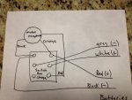
12V/24V Wiring

babymaker

Recruit
Joined
Feb 24, 2013
Messages
5
I have an older Motor Guide 44lb thrust motor with 12V and 24V switches on the motor. There is also a run/charge switch at the front of the boat and another switch for Batt 1 and Batt 2 at the front of the boat. I have 2 sets of pos/negative wires (4) going to the rear of the boat to the batteries. The motor only runs when I switch on the 24 v switch on the motor, and I run it off of one battery. Can I run/should I run 2 batteries? Will it be faster with 2 batteries? How do I use the switches at the front of the boat-run/charge and Batt 1/Batt 2? Thanks for any help. Boat is 31 years old and still running good. Just want to use the electric motor the best that I can and never have been sure on what to do with the switches at the front or the batteries.
 

gm280

Supreme Mariner
Joined
Jun 26, 2011
Messages
14,605
Re: 12V/24V Wiring

It is obvious that your trolling motor will run on either 12 or 24 volts being there is such a switch on it for those options. However, without seeing your wiring layout it is hard to tell if it is wired correctly to allow those options. The fact that you stated that it only runs when switched to the 24 volt position but you are only wired to one 12 volt battery leads me to believe it is either wired incorrectly OR the 12 volt circuit is not working... More information and some pictures would be great...
 

Silvertip

Supreme Mariner
Joined
Sep 22, 2003
Messages
28,771
Re: 12V/24V Wiring

It is impossible to help you with any degree of accuracy since a battery 1 & 2 switch is not typically part of this system so we can't tell what the wiring looks like. Draw a diagram and post it here. As for the batteries, you must have two batteries to get full power out of the motor for operation on 24 volts. It will run with the switch in the 24 volt position with only one battery but that is not a normal setup. If you want to use only the 12 volt setting then the wiring needs to be looked at.

With a 12/24 system each battery has a pair of wirings going to the panel at the bow of the boat. One pair is typically red and black and the other pair is orange and black. The RUN/CHARGE switch on the panel allows you charge both batteries at once using a through the trolling motor receptacle using a single 12 volt battery charger. The RUN position connects the batteries in series and CHARGE position connects them in parallel for charging. You cannot charge series connected batteries with a single output 12 volt charger. The wiring to troller receptacle then feeds the motor where you make the 12 or 24 volt selection using the switch othe foot pedal. When using a four wire 12/24 volt system you need to make sure the ground wire for battery #1 is correctly wired at the panel so it must be paired with the red wire. The black wire going to battery #2 must be properly matched for the orange wire. In other words, don't connect the battery 1 black wire to battery 2 ground and vice versa.
 

babymaker

Recruit
Joined
Feb 24, 2013
Messages
5
Re: 12V/24V Wiring

It is impossible to help you with any degree of accuracy since a battery 1 & 2 switch is not typically part of this system so we can't tell what the wiring looks like. Draw a diagram and post it here. As for the batteries, you must have two batteries to get full power out of the motor for operation on 24 volts. It will run with the switch in the 24 volt position with only one battery but that is not a normal setup. If you want to use only the 12 volt setting then the wiring needs to be looked at.

With a 12/24 system each battery has a pair of wirings going to the panel at the bow of the boat. One pair is typically red and black and the other pair is orange and black. The RUN/CHARGE switch on the panel allows you charge both batteries at once using a through the trolling motor receptacle using a single 12 volt battery charger. The RUN position connects the batteries in series and CHARGE position connects them in parallel for charging. You cannot charge series connected batteries with a single output 12 volt charger. The wiring to troller receptacle then feeds the motor where you make the 12 or 24 volt selection using the switch othe foot pedal. When using a four wire 12/24 volt system you need to make sure the ground wire for battery #1 is correctly wired at the panel so it must be paired with the red wire. The black wire going to battery #2 must be properly matched for the orange wire. In other words, don't connect the battery 1 black wire to battery 2 ground and vice versa.


I will check later on how wires feed to panel at front of boat. I just know that there are 3 wires going from motor to receptacle and 4 wires going to battery compartment (2 positive and 2 negatives). Thanks
 

Silvertip

Supreme Mariner
Joined
Sep 22, 2003
Messages
28,771
Re: 12V/24V Wiring

The three wires to the motor are 24 volts, 12 volts, and ground
 

babymaker

Recruit
Joined
Feb 24, 2013
Messages
5
Re: 12V/24V Wiring

wiring.JPG

I am not an electrician but this is a drawing of what I have with receptacle for trolling motor and run/charge switch pictured. I have 2 sets of pos/neg wires going to battery compartment at stern of boat. Does this help? Thanks.
 
Top