18 HP Wiring Diagram

Joined
Jun 11, 2013
Messages
53
Hi,
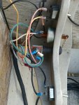
Does anyone here have the wiring diagram for a 1961 FDL-15 electric start with electric choke?
PO has it wired up so you use the momentary choke switch to activate the starter, and a combination key switch and toggle switch to shut it down. Quite the mess. The boat does have the correct Johnson solenoid assembly and wire harness.I suspect the key switch may be a generic one from a riding lawn mower. Any help would be very much appreciated. Thank you.
 

Joe Reeves

Supreme Mariner
Joined
Feb 24, 2002
Messages
13,262
I don't have the wiring diagram... BUT... if you purchase (or have) the standard ignition switch of today whereas the key is pushed in to activate the choke and has the six terminals on its back portion that state "A, B, C, M, M, S" and let us know what color wires lead out of the front of that wiring harness, I'm sure one of us (or all of us) could tell you how to wire it.

A = Accessory - 12v when key is ON or in START position.
B = Battery - 12v supply applied from battery (fused 20amp).
C = Choke - 12v applied to choke solenoid when key is pushed in.
M = Magneto - Black lead from one set of points.
M = Magneto - Black lead from other set of points.
S = Solenoid - 12v applied to small 3/8" nut terminal of starter solenoid when key is in START position.

NOTE:
The "M" terminals are connected when the key is OFF (Points shorted, No ignition)
The "M" terminals are disconnected when the key is in the ON or START position (Points NOT shorted. Ignition engaged)

That should get'ya started! :)
 
Joined
Jun 11, 2013
Messages
53
Thank you Joe Reeves! This is very helpful!
I don't at this time have the correct ignition switch, but will order one up asap.
The wire colors are: 2 Black, 1 Brown, 1 White, and 1 Green.
The choke solenoid no longer functions due to an open in the winding (and is no longer available), but this is not an issue as I use a tiller to steer and throttle the engine so using the manual choke is no inconvenience.
 

Joe Reeves

Supreme Mariner
Joined
Feb 24, 2002
Messages
13,262
The wire colors are: 2 Black, 1 Brown, 1 White, and 1 Green.
The choke solenoid no longer functions

The ignition switch I spoke of (Part # 508180), to my knowledge, will work fine with any outboard ever made.

Unfortunately that color "Brown" is foreign to me.

But I assume the Black leads are connected to one set of points each (check it though), and if so, they will connect to one wire for each "M" (magneto) switch terminal.....

The White wire, if that leads to the small 3/8" nut of the starter solenoid, would connect to the "S" (solenoid) switch terminal.....

And the Green wire (if that is a 12 supply lead) would of course connect to the "B" (battery) switch terminal.

The Brown wire... don't have a clue... choke wire?
 

derek4325

Petty Officer 2nd Class
Joined
Mar 7, 2015
Messages
160
Looks like Joe has you covered for your ignition switch. That being said those choke solenoids are pretty readily available. You can go to marineengine.co m and look up a diagram and get the part # for your solenoid and look that # up on ebay. OR (and this is the one i recommend because he has been very helpful for me) laings oitboard... look up the website and give him a call. I would bet a paycheck he has one and anything you might need with it. He may even have a good used harness for you too but you will probably pay for it. Youre on the right track using a regular harness for a lawn mower. Good luck!
 

lindy46

Captain
Joined
Nov 27, 2008
Messages
3,886
The brown wire is most likely the choke wire. Is it possibly red, just discolored with age?
 
Joined
Jun 11, 2013
Messages
53
lindy46 I think you may be correct.
The brown looking wire was probably red once upon a time.
I can't complain though.
Everything on this boat is from the early 60s and still worked well even with this messed up electrical configuration.
 
Joined
Jun 11, 2013
Messages
53
Ok. I ordered ignition switch 508180 and it will be here in a couple of days.
I'll let you all know how it turns out.
 
Joined
Jun 11, 2013
Messages
53
I got a late start and ended up finishing in the dark, but I have the new switch in and all the old cobble job out.
While I was at it I decided to tidy up the wire harness.
Here are before and after photos.
I'll install the battery in the morning and test it all out, but I'm confident that all is wired correctly.
The remaining toggle switch is for the lights.
I'll be replacing it with a double throw switch so in one position all the lights will be on and in the other only the anchor light with center being the off position.
Thanks to everyone for your assistance, and a special high five to Joe Reeves for making this so easy.
 

Attachments

  • photo299521.jpg
    photo299521.jpg
    681.6 KB · Views: 1
  • photo299522.jpg
    photo299522.jpg
    584.8 KB · Views: 1
Top