196x Johnson 35 / 33

catbones

Petty Officer 1st Class
Joined
Jul 15, 2012
Messages
319
I'm going to post this here also and see if anyone can help. Long story short, I restored a 1967 StarCraft with a 196x I think Johnson 33 or 35... However I'm having a hard time with wiring it.

The new switch I got has 6 points, B, C, A/M, M, I and S.

I've moved everything so far from old switch to new which was B, S, M and M/A.

Motor starts fine but when I turn the key into the OFF position, it won't kill. Any suggestions???

Here's the switch photo.

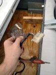
I'm also left with a white wire, a red wire and a thick brown wire... Is one the ignition and choke?

Here's the second photo of the wires I'm left with. Pick #2.

Pick #3 just to confirm, the light brown wire in the picture with the white connector ... Anyone know where that goes. Found a connector on the main box with a fuse and that thick brown wire .. So I connected to that but not sure what either one is.

Hell??
 

Attachments

  • photo227693.jpg
    photo227693.jpg
    40.1 KB · Views: 0
  • photo227694.jpg
    photo227694.jpg
    27.6 KB · Views: 0
  • photo227698.jpg
    photo227698.jpg
    154.9 KB · Views: 0

F_R

Supreme Mariner
Joined
Jul 7, 2006
Messages
28,226
A picture is worth a million words. See next posting
 
Last edited:

F_R

Supreme Mariner
Joined
Jul 7, 2006
Messages
28,226
No Title

Better yet......
 

Attachments

  • photo227700.jpg
    photo227700.jpg
    214.1 KB · Views: 0

catbones

Petty Officer 1st Class
Joined
Jul 15, 2012
Messages
319
Better yet......

Thanks for the diagram... Per it, seems I got it all good, however my red goes to a bulb something, that also has a white, which is confusion when it should go to choke... Per diagram. Now I've got the two blacks connected to M but it doesn't kill the engine in off position, possible that I got them switched why it's not killing the motor. Thanks for the help already...
 

silver_bay

Petty Officer 3rd Class
Joined
Aug 5, 2010
Messages
99
The page for the amazon link you gave has "merc" in the title?!

The OFF (kill) position should connect the two "M" terminals (which shouldn't connect to anything else in any (other) switch position)
 

catbones

Petty Officer 1st Class
Joined
Jul 15, 2012
Messages
319
The page for the amazon link you gave has "merc" in the title?!

The OFF (kill) position should connect the two "M" terminals (which shouldn't connect to anything else in any (other) switch position)

Is it possible that I should flip the M wires... Is there a certain way? I'm thinking I might have the M wires the opposite .. Top should be at bottom and bottom at the top M...
 

F_R

Supreme Mariner
Joined
Jul 7, 2006
Messages
28,226
It doesn't matter which "M" terminal goes to which black wire. Reversing them won't make any difference.
 

F_R

Supreme Mariner
Joined
Jul 7, 2006
Messages
28,226
Refer to the diagram. The thick brown wire is not used unless you have a generator. But now I'm wondering--DO you have a generator? One of your pictures seems to show the thick brown and thick green spliced together. Somebody might do that if they have a generator but no ammeter. The light socket with a thin tan wire is an overheat warning light. All this makes me think we are talking about the wrong motor here. Are you sure you don't have a 40 hp?
 

F_R

Supreme Mariner
Joined
Jul 7, 2006
Messages
28,226
Concerning the motor won't kill when you turn the key off: You will have to check those two black "M" wires all the way back to their source on the motor. There is a break somewhere, or one is not connected somewhere. Shade tree mechanics are notorious for disconnecting them at the vacuum cut-out switch, with the mistaken notion there is something wrong with it.
 

F_R

Supreme Mariner
Joined
Jul 7, 2006
Messages
28,226
No Title

Concerning that unused white wire: I believe it actually is grey and is a tachometer ground wire. Another indication it is a 40hp. At least the cable is. I don't kknow what the motor is. How about posting some pictures of the motor with the hood off? Here is the 40hp diagram. I have over 100 diagrams, but have to know what motor you have if I am to post the right one without guessing
 

Attachments

  • photo225488.jpg
    photo225488.jpg
    193.9 KB · Views: 0

catbones

Petty Officer 1st Class
Joined
Jul 15, 2012
Messages
319
Now that would be very interesting... I got the boat and motor from an older guy, who said he was going to replace, whatever .... The bottom mount serial and model states its a 33EL 69, if it makes any sense.

I took it on the water today for a little besides the fact that the switch won't kill the motor but a choke pull will. It ran but it was rough and having it in forward but at down slow in the control box it just kept dying unless I slightly shifted it to higher rpm or whatever you want to call it on the control nob. So after this, I'll need some help tweaking so it runs little smoother. I'm guessing older guy didn't care about it much.

Here's some pics of me mounting it, if not enough let me know;


catbones

Petty Officer 1st Class
Joined
Jul 15, 2012
Messages
319
Here's also what's interesting ... The wires going from the red plug, that connect to the other red plug in the motor... I see a white, brown, purple with white stripe and red... Like in the photo.


However down the road at the plug, I don't see any purple at least or red, etc... Could thenold guy splice and connect something else to it which is why the wires don't match up color wise? However it worked perfectly before I took the boat to rebuilding. Still does, other then shitting itself down with the new switch. If I really have to I'll go and test with old switch see if it shits down.


F_R

Supreme Mariner
Joined
Jul 7, 2006
Messages
28,226
No Title

Crap, no wonder you are confused. That is a 1969 33hp. It isn't even supposed to have a junction box. That's what happens when somebody assembles a box of misc parts and tries to make a motor out of it. I'll post the correct diagram. Follow it.
 

Attachments

  • photo227808.jpg
    photo227808.jpg
    170.4 KB · Views: 0

catbones

Petty Officer 1st Class
Joined
Jul 15, 2012
Messages
319
Crap, no wonder you are confused. That is a 1969 33hp. It isn't even supposed to have a junction box. That's what happens when somebody assembles a box of misc parts and tries to make a motor out of it. I'll post the correct diagram. Follow it.


Thanks! yeah.... looking closer its all mixed up. So if I understand correctly, I don't need this box with the starter solenoid either?


you wouldn't know where I could get a newer cable from some where to clean this up a bit..
 

catbones

Petty Officer 1st Class
Joined
Jul 15, 2012
Messages
319
That's what I thought looking at the motor a year ago before storage and sort of went "huh same thing here and same thing here, why two?" ... that's the solenoid I was looking in two places.

Wish there was a good place to get replacement wire/cable that actually matches and just unplug that one and plug this one in.
 
Top