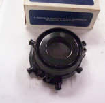
1971 Johnson 60 HP No Spark.

Oconnor1usa

Recruit
Joined
Jul 25, 2022
Messages
3
Can someone tell me how the 2 point's on the 1971 60 hp control 3 Cylinders?

Also, I would like to verify the spark plug wire to rotor/stator assemble locations.
According to the service manual illustration the center receptacle on the starter side of the motor crosses over to the coil. Verified through Pic
the receptacle on the opposite side ( CDI box side) seams to go to #2 middle Cylinder?
Receptacle at front of motor #1 go to the center piston
remaining Receptacle furthest aft, go to the bottom piston?
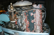
1658773160055.png
 
Last edited:

F_R

Supreme Mariner
Joined
Jul 7, 2006
Messages
28,226
There are 3 lobes on the cam for the 3 cylinders. One set of points "makes" the circuit, other set "breaks" the circuit. Easy to see if you watch them closely while slowly rotating the crank.
 

Oconnor1usa

Recruit
Joined
Jul 25, 2022
Messages
3
There are 3 lobes on the cam for the 3 cylinders. One set of points "makes" the circuit, other set "breaks" the circuit. Easy to see if you watch them closely while slowly rotating the crank.
Thank you for the fast response.
The two point assembles are connected on the back side by a wire on the plate side and checking for continuity during the cycling, when one is high on the lobe, the other is ~midway between lobes and closed. Then as point one's arm exits it's lobe, the second climbs and opens.

When I put the ohms meter across the wire connector as expected it shows continuity through out the 360 degree rotation.
Now this is where it gets weird.
When I touch Point one base side and crank side as expected continuity when shut, open when open.
When I touch the point one base side and crank side of point 2 as expected continuity because between lobes and .10 gap is closed on point two thus chased back through the wire connection,

Now when I touch the base side point 2 and crank side of point 2 as expected continuity because between lobes and .10 gap is closed, as it rotates it opens and continuity is lost as expected.
Repeating the first set up, Point one base side or crank side when lobe rotates and points close, continuity as expected.

However, over time it appears as I feel you are explaining the two combine and act as a pulse signal every 120 degrees.
So the points act as the "trigger", but what is determining the path to the proper cylinder.
 

F_R

Supreme Mariner
Joined
Jul 7, 2006
Messages
28,226
A pulse every 120 degrees is correct. However, that is not the diagram for the ignition system your motor came with.

The spark is sent to the proper cylinder by the distributor rotor.
 

Oconnor1usa

Recruit
Joined
Jul 25, 2022
Messages
3
A pulse every 120 degrees is correct. However, that is not the diagram for the ignition system your motor came with.

The spark is sent to the proper cylinder by the distributor rotor.
Understand, that is for a single cylinder.
Now, on a normal distributor rotor and cap, charge is transferred to each spark plug as the rotor passes the conductor and thus spark plug associated with that charge.
Since my distributor/stator assembly has no conductive interface for each cylinder, as it passes it 120* interval, this however has insulation surrounding the 3 plug assemble.
So is the charge inductively coupled? LOL.
1658785801079.png
A pulse every 120 degrees is correct. However, that is not the diagram for the ignition system your motor came with.

The spark is sent to the proper cylinder by the distributor rotor.
 

racerone

Supreme Mariner
Joined
Dec 28, 2013
Messages
38,805
Each post has a number on it.-----The leads are threaded into the cap.----What is your motor doing / not doing ?----Please do not compare these things to an automotive distributor !----This motor is 50 years old and I assume it was running in those years.-----Must not be anything wrong with the design.----It was short lived because a better design ( magneto driven ) came out with the 2 cylinder 50 in 1971.-----Also put on the 72 model 3 cylinder.----What is your motor doing / not doing ??-----You need to look carefully at the rotor and the distributor cap !!-----It should then be obvious how it works.-----And no it is not " inductively coupled " what ever that means.
 
Last edited:
Top