1972 evinrude 85hp no spark

Status
Not open for further replies.

JOEjones31989

Seaman Apprentice
Joined
Jul 7, 2015
Messages
34
OK I have a 1972 evinrude 85hp I had it out last Friday running across the lake at WOT then out of no where it just shut down no sputtering or anything before it died. Try starting it back up out there but nothing so I got it home checked spark and nothing. Took flywheel off checked and cleaned everything under flywheel. The stator ohmed out good. I'm thinking it's the CDI box but want to ask others before I pay 400 dollars for a new one. I read somewhere you can pull the switch wire and try to start it by jumping the the starter but I can't figure out wich wire I need to pull off the cluster on the back side of the. Motor..... any tips suggestions would be amazing thank you for the time to read and help out.
 

F_R

Supreme Mariner
Joined
Jul 7, 2006
Messages
28,226
EDIT: Oops, forget what I just wrote (and deleted). Was thinking the wrong year. '72 has the battery CD system. You have to follow an orderly troubleshooting procedure. You are thinking right-- do not replace the amplifier until you prove by power of elimination that it is bad.

EDIT again: Don't bother buying a factory service manual to troubleshoot it. The method they give is obsolete. You need to know how the system works and use common sense.
 
Last edited:

JOEjones31989

Seaman Apprentice
Joined
Jul 7, 2015
Messages
34
yes, where would one find information on how the system works ive got the basic knowledge of how its working from being a mechanic all my life but trying to figure out the wiring on the wire cluster has got me in a bind since its not to easy to chase half the wires and theres no wire diagrams that i have found for a 72. the main wire im trying to find right now is the "kill switch" wire i believe is what they call it.... or the safety switch wire..... i do know its the wire that pretty much allows you to bypass the starting switch and everything else past the motor.... there for allowing you to elimate faulty switch, bad connections etc. past the motor...... or even some specs on the voltage at certain parts through out the motor would work to help me narrow down the issue and pinpoint it.
 

F_R

Supreme Mariner
Joined
Jul 7, 2006
Messages
28,226
No Title

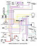
Joe, you are making the mistake of confusing the '72 with a '73-up. There is no "kill" wire on a '72. It is powered by battery voltage coming from the ignition switch. So first step is to check the voltage at the amplifier input (purple wire at the terminal strip).

I could explain the whole troubleshooting routine, but I just don't have time right now to type a book. Come back Sunday if you don't have it yet. In the meantime, here is the wiring diagram
 

Attachments

  • photo241822.jpg
    photo241822.jpg
    253.2 KB · Views: 14
Last edited:

JOEjones31989

Seaman Apprentice
Joined
Jul 7, 2015
Messages
34
ahh well that makes alot of sense on why i was getting confused and couldnt find that wire. on the diagram i know the purple wire going into the amplifier is getting power 12V or there abouts going off memory since i did this last weekend. and if i disconnected the gray/white wire going to the anti reverse term. i could hear clicking in the amplifier...... but that darn blue wire going to my coil is whats getting me...... im not sure if i should be checking that in A/C or D/C for voltage and i have no clue what its suppose to be reading..... but thinks for your help, i will check back sunday afternoon.
 

F_R

Supreme Mariner
Joined
Jul 7, 2006
Messages
28,226
I think you know enough that I probably don't have to write a book. You have about 12V to the amplifier, so let's assume everything is ok up to that point. Next thing is to decide whether the amplifier or coil is at fault, or is the spark getting lost in the distributor cap. Disconnect the blue wire, then unbolt the coil and unscrew the spark wire from the dist cap. Reinstall the coil and rig up a spark gap from the end of the disconnected spark wire. Disconnect the black/white striped wire. Turn the key on. Now lightly brush the striped wire across an unpainted grounded item. You should get a flurry of sparks across the gap at the end of the spark wire. If you do, the amplifier and coil are capable of doing at least something, and the trouble most likely is under the flywheel.

As for the blue wire, that would be very fast DC pulses. The original method of checking was with a now obsolete neon tester. Now the preferred method is with a DVA meter (peak reading voltmeter). The pulses are way to fast for a regular meter to respond and produce a reading. A peak reading meter detects the pulses and stores the result long enough for you to get a reading. To tell the truth, I don't even know what the reading should be--somewhere around 300V I think. In any case, you should not be trying it with the blue wire disconnected. Possible amplifier damage could occur.

In fact, that system is very touchy concerning loose connections, especially in the battery, battery cables and connections and alternator wiring. High voltage spikes from loose or arcing connections spell death to the amplifier.

Briefly, how it works, is 12V is supplied to the amplifier, and the amplifier increases it to about 300V and stores it in a capacitor until time to fire a plug. The breaker points making and breaking a ground on the striped wire are what tells it to fire, each time the ground contact is broken. When the ground contact is broken, the 300V stored in the capacitor is discharged through the primary winding of the coil, and the coil increases that 300V to whatever it takes to fire the plug. The distributor does just what a car distributor does, point the spark to the proper plug wire. I might add that the distributor is a POS in my not so humble opinion. The anti-reverse cutout ring grounds out the points wire if the engine tries to run backwards. Yes, it can run backwards. The ring should be lubricated very sparingly with HT grease where it rides on the crankshaft. Breaker points should be gapped at .009" to .010". Very critical.

Coil primary and secondary windings can be tested for continuity/resistance with an Ohm meter. But again, I don't remember what the expected resistance readings should be.

Hope this helps at least a little bit.

EDIT: That should be "EP" (extreme pressure) grease on the cut-out ring.
 
Last edited:

JOEjones31989

Seaman Apprentice
Joined
Jul 7, 2015
Messages
34
well that makes since why i wasnt picking nothing up with my Volt meter on the blue wire, ill have to try and track down a DVA meter to test that out. and yea i am not impressed with the system under the flywheel..... when i looked at it last weekend my first words was wow not what i expected on a out board motor... but i will deffently look at it some more tomorrow. thank you for the run down on this system.
 

durban

Master Chief Petty Officer
Joined
May 27, 2011
Messages
894
I have a 100hp 1971 with the Amplifier & points system the amplifier packed up so i just converted it using a 1974 Toyota HT Coil & ballast resistor which you connect in series between the ignition switch & Coil then also you have to use a 20 nf or 24 uf condenser as there is no place under the flywheel to connect the condenser just connect it to the negative on the the coil all this i bought from the scrap yard for 20 dlrs . it starts first time and every time :joyous:
 
Last edited:
Status
Not open for further replies.
Top