2000 Evinrude FICHT Tilt and Trim will not work

rlaft

Cadet
Joined
Apr 29, 2022
Messages
6
2000 Evinrude 225hp motor tilt trim will not operate. The PDP has been rebuilt, relays work when switch is pressed both ways, power down to the motor, motor works when connected to a 12v battery source.

What else could be the problem. Could it be the trim sending unit, trim limit switch?

Any help advice is appreciated.
 

racerone

Supreme Mariner
Joined
Dec 28, 2013
Messages
38,800
Trim limit switch stops motor from trimming too high.----Sending unit has nothing to do with motor operation.
 

Crosbyman

Vice Admiral
Joined
Nov 5, 2006
Messages
5,784
what does ... "power down to the motor" mean ?

are you saying power is sent down to the motor when you activate up or down toggle switches and yet the motor does not work ? and yet the motor runs ok if fed direct battery voltage on the wires going into the motor.

trimming draws lots of amps and all the relays do is feed bat and grd one way and reverse the other way.... relays may click ok but any resistive path on the B+ supply may supply enough juice for relays to click but fail to deliver big amps for the motor itself.

check all connection points, check the fuse pins and socket for oxydation . The fuse gets +12 of the solenoid. check those connections also.
 

Attachments

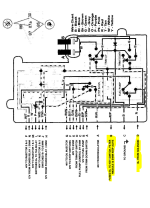
  • EV 2000 T&T diagrams.pdf
    300.1 KB · Views: 14

rlaft

Cadet
Joined
Apr 29, 2022
Messages
6
what does ... "power down to the motor" mean ?

are you saying power is sent down to the motor when you activate up or down toggle switches and yet the motor does not work ? and yet the motor runs ok if fed direct battery voltage on the wires going into the motor.

trimming draws lots of amps and all the relays do is feed bat and grd one way and reverse the other way.... relays may click ok but any resistive path on the B+ supply may supply enough juice for relays to click but fail to deliver big amps for the motor itself.

check all connection points, check the fuse pins and socket for oxydation . The fuse gets +12 of the solenoid. check those connections also.
When I replaced the motor, trying to bleed the system, tilt trim worked for 2 or so minutes and then cut out. Now it won’t work?
 

rlaft

Cadet
Joined
Apr 29, 2022
Messages
6
When I replaced the motor, trying to bleed the system, tilt trim worked for 2 or so minutes and then cut out. Now it won’t work?
Yes switches pressed 13.2 volts to the motor, motor will not turn. Connect motor straight to battery motor spins.
 

Crosbyman

Vice Admiral
Joined
Nov 5, 2006
Messages
5,784
13.2 volts is the voltage you read at the open end of your 2 wires and that is because it is the HIGHEST point of resistance in the wiring... open air

what is missing are amps....stuck somewhere along the wiring is some resistive connection that will allow you to measure that voltage but no amps can properly flow to reach the trim motor.


Could be anything.... between the battery posts and your trim motor.

look for oxydized crimps, rotten wires under the insulation, coroded junction points.

connect up your trim motor try to get it going by pressing up or down switches while..... poking tapping twisting the wiring from battery crimp joints, B+ solenenoid connection points, fuse socked , relay sockets etc...

resistive connection genetare heat ...feel around to see if any wires or connections get warm or hot...or start smoking :) while holding that trim switch activated

have friend hold the trim switch while you poke around and btw how's the start circuit does the starter spin ok ??.
 
Last edited:

rlaft

Cadet
Joined
Apr 29, 2022
Messages
6
13.2 volts is the voltage you read at the open end of your 2 wires and that is because it is the HIGHEST point of resistance in the wiring... open air

what is missing are amps....stuck somewhere along the wiring is some resistive connection that will allow you to measure that voltage but no amps can properly flow to reach the trim motor.


Could be anything.... between the battery posts and your trim motor.

look for oxydized crimps, rotten wires under the insulation, coroded junction points.

connect up your trim motor try to get it going by pressing up or down switches while..... poking tapping twisting the wiring from battery crimp joints, B+ solenenoid connection points, fuse socked , relay sockets etc...

resistive connection genetare heat ...feel around to see if any wires or connections get warm or hot...or start smoking :) while holding that trim switch activated

have friend hold the trim switch while you poke around and btw how's the start circuit does the starter spin ok ??.
Starts up no problem.
 

Crosbyman

Vice Admiral
Joined
Nov 5, 2006
Messages
5,784
that says the battery wiring to engine ground and solenoid /starter are ok and....will carry enough amps for the trim motor .........when the wiring /relays are fixed. check any interupt devices or bypass them tempotarily as a test .

open all connectors to the front controls/display if any trim should work by itself withouthe front controls on the throttle/shifter

focus on the rest of the wiring ex: solenoid connection feed to the relay block assembly
and relay block wires to the trim motor connector, relay socketsand relay pin contacts. etc...

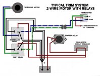
see basic 2 wire trim
 

Attachments

  • 2-wire-Trim.jpg
    2-wire-Trim.jpg
    99.9 KB · Views: 9
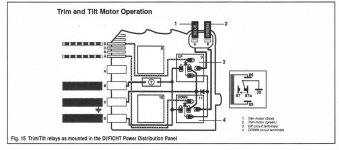
  • FICHT  T&T diagram.JPG
    FICHT T&T diagram.JPG
    56.7 KB · Views: 11
  • ficht PDP.PNG
    ficht PDP.PNG
    120.8 KB · Views: 10
Last edited:

Crosbyman

Vice Admiral
Joined
Nov 5, 2006
Messages
5,784
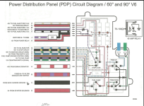
btw what was wrong with your PDP ?? the bottom D input feed of 12v has a history of cracked or cold solder joint easy to reweld if you are handy at this.

since your T&T relays get their +12 source directly off the PDP it is possible your PDP is still defective. It may let enough +12 to be distributed for lesser amperage hungry ept...but not your T&T motor. see if anything happens if you tap the panel itself while trying to trim.

here is a better shot and has you can see there is not much between a strong +12 DC input at "D" and output of DC and GRD distrubution ..... from the relays to the trim leads.
 

Attachments

  • PDP ficht 2002.PNG
    PDP ficht 2002.PNG
    376.8 KB · Views: 9
Last edited:

rlaft

Cadet
Joined
Apr 29, 2022
Messages
6
that says the battery wiring to engine ground and solenoid /starter are ok and....will carry enough amps for the trim motor .........when the wiring /relays are fixed. check any interupt devices or bypass them tempotarily as a test .

open all connectors to the front controls/display if any trim should work by itself withouthe front controls on the throttle/shifter

focus on the rest of the wiring ex: solenoid connection feed to the relay block assembly
and relay block wires to the trim motor connector, relay socketsand relay pin contacts. etc...

see basic 2 wire trim
So I have four trim switches. The one in the motor, the switch on the throttle, one on the steering wheel and one at the bow. When the rain stops I will try all of them. Haven’t been able to test anything for a few days.
 
Top