2011 E-tec Evinrude 15hp

sec56

Seaman
Joined
Mar 19, 2011
Messages
61
I bought this used last year complete with controls and harnesses. I have a few questions regarding 2 wires which the previous owner cut off because they were grouped with some other wires, a four pole connector an a single red wire. I believe the single red wire probably goes to the fuse panel as a supply wire. The blue wire with the white stripe and the black wire are the two wires the previous owner cut off. Looking at different wiring diagrams, I was thinking they might go to the warning horn, but today I saw a "common wiring color chart" as it was called which makes me believe blue/white wire could be a trim wire. The four pin connector, I have no clue at all. Any help with this matter would be greatly appreciated.
 

Attachments

  • photo311068.jpg
    photo311068.jpg
    131 KB · Views: 0
  • photo311069.jpg
    photo311069.jpg
    158.3 KB · Views: 0
  • photo311070.jpg
    photo311070.jpg
    283.3 KB · Views: 0
  • photo311071.jpg
    photo311071.jpg
    317.5 KB · Views: 0

jakedaawg

Rear Admiral
Joined
Jun 26, 2012
Messages
4,275
List all 4 wire colors but it looks like one is wht/gold stripe. That's trim position. This plug goes to the instrument cluster. It also may not be relevant on a 15...never rigged one that small. Heck, l didnt know they made little ones that small.
 

sec56

Seaman
Joined
Mar 19, 2011
Messages
61
I do have an OEM service manual for my 2011 E-Tec Evinrude 15hp. The wiring diagrams at first weren’t being that helpful to me. The one I've be paying particular attention to is titled MWS DASHBOARD. For some reason this wiring diagram wasn’t making sense. I may have been over thinking this. Looking at this wiring diagram again as I type this post, it shows the purple wire, 12v supply from the ignition switch, is attached to the “I” terminals on the trim meter and volt meter (all gauges with an “I” terminal). The attached wiring color code chart says the purple wire is the 12v positive wire from the ignition switch. Makes sense that you wouldn’t necessarily want gauges active with the key off. And the white/tan (white/gold as I saw it) wire connects to the “S” terminal on the trim gauge, just as you said jakedaawg. The gray wire would be the tachometer signal to terminal “PUL” on the tach. The black wire is attached the all “G” terminals (ground).
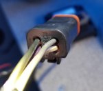
See new attached images. I've labeled each position and wire colors. Hope the print on the pictures isn't too small, but just in case they are as follows by the number on the connector: 1.) Purple, 2.) Black (I would expect to be ground), 3.) Gray, and 4.) White with gold or tan stripe. All the colors fit per the listings in the above.
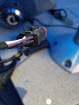
Now on my shift/throttle lever there is a trim up/down rocker switch which plugs into the harness but if memory serves me correctly, it's a 3-prong triangular connection with green, blue and red wires circled in red. I'll have to go check those colors again, see picture numbered 4.
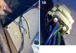
After seeing the wiring color code chart that I found online, it says “Trim Up Switch” wire is blue with a white stripe (possibly solid blue), and the “Trim Down Switch” is green with a white stripe (possibly solid green). In the picture I numbered “5A,” the blue/white wire and the black wire plug into a solid blue and a solid green wire. From what I see here, I’ve been working with the wrong wire colors. It should have been solid blue and solid green. Can you or anyone else tell me if the item in picture 5B is the tilt/trim relay? Do you need a better picture to tell? I have a rocker switch on the shift lever for tilt/trim which I think is active (don’t know yet since its not been powered up yet). Now in this connector circled in yellow, shows the blue/white wire paired up with the solid green wire, and the black wire paired up with the solid blue wire. My best guess is one is positive and the other is ground. Can anyone tell me if my line of thought is correct? Can anyone tell me which is positive and ground or doesn’t it matter because of what I think is a relay?
The primary reason I bought the motor was for the tilt/trim feature. I have a Crestliner 2360 Eagle SST with an extended transom. It’s a long reach to tilt the previous 1984 Johnson 9.9 back there. Anyway, thanks again for any input. Have a great day.
 

Attachments

  • photo311235.png
    photo311235.png
    93.4 KB · Views: 0
  • photo311236.jpg
    photo311236.jpg
    328.2 KB · Views: 0
  • photo311237.jpg
    photo311237.jpg
    566.2 KB · Views: 0

jakedaawg

Rear Admiral
Joined
Jun 26, 2012
Messages
4,275
Having a hard time understanding what the question is. Are you having an issue getting the tilt working?
 

jakedaawg

Rear Admiral
Joined
Jun 26, 2012
Messages
4,275
Blue is up. Green is down. If they have a stripe they are on the fused side usually but some times that's not the reason for the stripe.

so, from the control you have a 3 pin plug w/ green, blue, and red. This should plug into the main harness. I think there is only 1 plug it fits in. They may or may not be stripped, it doesn't really matter. This is the plug that does the t-n-t.

the 4 pin plug goes to the instruments. There may be others that go to a system check tach or the system check oil/no oil/chk engine stand alone guage/warning horn.

blk is ground but dont just ground anything to it.

red is 12v

red w purple stripe is probably fused power 12v.

purple is keyed 12v but just meant for guages, not accessories usually.

usually you do not want to cut and splice these wires, all the plugs are there. Run a seperate hot and ground to a fused bus bar for accessories. Keep them off engine control curcuits.

edit to add disclaimer: it's been quite some time since I've rigged an etec, above is from memory so accuracy may not be perfect
 
Last edited:

jakedaawg

Rear Admiral
Joined
Jun 26, 2012
Messages
4,275
Usually the trim and tilt relays are on the motor. There was a time when there was an additional relay in the harness but I thought that was just on the four strokes. It's possible that is a relay as it has the correct amount of wires but I just don't know on these small motors. Maybe Faztbullet will see this
 

sec56

Seaman
Joined
Mar 19, 2011
Messages
61
Here's an update on my installation progress. Those 2 wires that were cut off (black, and blue/white) are for a remote tilt/trim switch. The 4-pin connector isn't necessarily needed, depends on if gauges such as tilt/trim or a non-system check tachometer is going to be used or not. I still have to wire in a tilt/trim gauge. I found a 4-pin connector with pigtail (looks to bean exact match), 14awg wire, male and female (states made in USA), is available through Amazon for $14.00 which I have ordered. That way I don't have to cut any wires nor do I have to put it together. Only wire I won't be using is the one for the non-system check tach since I installed a system check tach. I did have the engine running, but it would only run up to 1000rpm. After reading more about the engine again, it sounds like it's on safe mode. The Lights on the EMM during start up and running are as described in manual as being good, no issues. One thing I did come across was if the engine is started outside of the neutral position, it will be in safe mode, that is if I understood what I read correctly. I'll have to recheck that with a fresh pair of eyes and mind. It may have to go to an Evinrude dealer for further service. But, before I forget, I want to thank everyone, especially jakedaawg for their help. I still have to change the lower unit lube. Have a great day.
 
Top