7.4GL Volvo Penta 1994 Regal 256 Valanti Full Cooling system Diagram needed

mmoreno

Recruit
Joined
May 1, 2015
Messages
5
Hello, I am new to the industry and new to this forum. I am looking everywhere, purchasing manuals, scouring Google and cannot find a diagram that will show me the systematical way to connect all the water hoses for the system. It's a front mount full system. I purchased the boat with a lot of work still needed. The hoses they supplied just don't seem to fit anywhere that makes sense. I know, I sound like an idiot but I am truly very mechanically inclined. I am just having a hard time locating any type of documentation on this set-up. On the Volvo Penta badge I have a product number 3868003 model DP serial number 4111503976. Any help would be so incredibly appreciated. Thank you!
 

mmoreno

Recruit
Joined
May 1, 2015
Messages
5
Wow! Thank you Wrench3!! This is amazing, and exactly what I need. Still learning all the correct terms so I apologize for that. Yes it's a closed cooling system and it differs from the schematic shown for carbureted 7.4L engines. Unfortunately when the motor was pulled out and sent to the engine shop to be completely overhauled they didn't take any pictures of the setup prior to removing everything. Story is I bought this boat off my boss who was trying to restore it but ran out of patience. Fortunately for me I was the one who was having to order all the parts he was needing while not busy in our IT department. Everything is either replaced with Brand new equipment or was in process of doing so. I believe I have the cooling system correctly installed for proper flow but will have to wait and see once I get it started. I believe I have a bad oil pressure sensor as it is not passing 12 volts out of one of the pins sending 12 volts to a relay powering the 12 volts on the coil. Learning as I go. I know, I probably lost you way before this so I want to say thank you for the link and hope that if the Flow on the system isn't working correctly maybe I can draw up a schematic and post it seeing if anyone can see where my fault is?
 

wrench 3

Commander
Joined
Aug 12, 2012
Messages
2,108
You could post a cooling system schematic now and get some input before something overheats.
I can't find a wiring diagram for your engine, but an oil pressure switch usually only passes current when oil pressure is present. And it doesn't sound like your running yet. They are usually hooked into the fuel pump, not the ignition coil.
 

bruceb58

Supreme Mariner
Joined
Mar 5, 2006
Messages
30,620
Just so you know, you need to look at the MD manual for your boat on the boatinfo site

The coil voltage comes from your ignition switch after it passes through you man overboard switch. No relay for ignition.

There is a relay for your fuel pump. It is energized during cranking from a wire that comes from the starter solenoid and from an alternator L output when the engine is running. each of those wires has a diode inline with it.
 
Last edited:

mmoreno

Recruit
Joined
May 1, 2015
Messages
5
Thank you guys, I will verify the wiring and check back in on that. I removed the Sensor last night and tested it putting a meter to the two contacts, supplied pressure to the backside of it and continuity was made so the sensor seems sound. The sensor was mounted on the back underside of the motor just above where the two oil lines go in/out to the filter assembly. I verified oil level, oil at the filter, yet no oil was present in the tube (lack of better phrase for location of sensor) which concerns me. My understanding is that oil pressure should be present in that location for the sensor to work? Side note: The motor was completely done from bottom up at a race shop with all new parts internal and external and was dyno tested with fantastic results. So I know that the oil pump is working. Maybe a blocked feed/supply line is blocked coming from the filter? Not sure. Checking tonight. AS for the Schematic I will draw up something and post it in hopes that it is correct. Haha. Please don't mock the 3rd grade artistic talent. Will check back with the results. This site is great!
 

bruceb58

Supreme Mariner
Joined
Mar 5, 2006
Messages
30,620
There is an oil pressure sender on your engine for your oil pressure gauge. There is no oil pressure sender/sensor that has anything to do with your ignition.
http://boatinfo.no/lib/volvo/manuals/md_elect.html#/132
Page 132

And it doesn't sound like your running yet. They are usually hooked into the fuel pump, not the ignition coil.
Like I said before, the fuel pump relay does not get energized by the oil pressure switch. This is a Volvo you are working on, not a Mercruiser that uses that other method.

The fuel system manual shows exactly what I am saying.
http://boatinfo.no/lib/volvo/manuals/md_fuel.html#/82
Page 82

If you just want to get the engine running until you sort your electrical out, just run a jumper wire between the postive post of your battery to the positive post of the coil.
 
Last edited:

mmoreno

Recruit
Joined
May 1, 2015
Messages
5
Okay, I am looking at the schematics in the manual and you are correct on the Sensor/sender unit. Unfortunately for some reason this Sensor when following the wire back goes to a set of relays where it powers #86 of the relay !2volts which when powered allows the relay to kick out 12 volts through #30 (output of relay) to the positive side of the coil. I'm not sure if this was done as a safety precaution by someone prior to me getting the boat and not factory installed. It sure looks factory though, none the less I will print out the book you provided and wire it as shown in the schematics. I thought I was alone in the world when I first started this project but it sure looks like I got a lot of people watching out for me and helping me along on this project. I really hope I can repay the effort some day. I will post a couple of pictures, one of the motor to show the cooling system which I believe by all the reading that it is a closed raw water system. I also have a picture of the sending unit as well.
 

mmoreno

Recruit
Joined
May 1, 2015
Messages
5
Well apparently I cannot post pictures yet. From the schematic in the book it looks like I have the water system flow correct and will see what I can do on the wiring. I will also verify what alternator I have as in if it's a five wire or not. I am working on it tonight and every night and weekend I can. Wish me luck.
 

bruceb58

Supreme Mariner
Joined
Mar 5, 2006
Messages
30,620
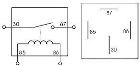
Typically, #30 is usually the power input to the relay. #86 is one side of the coil of the relay. #85 is the other side of the coil of the relay. 87 is typically the pin that is then the output.

Obviouslly, you can have either pin as the output or the input.

What you are describing is not standard for a Volvo. In fact, it is hard to imagine how you could even start your engine with that configuration.

4-pin-automotive-relay.jpg
 
Last edited:

wrench 3

Commander
Joined
Aug 12, 2012
Messages
2,108
Is there still a wire running directly from the ignition switch to the ignition coil? And what is feeding the oil pressure switch?
It's still not making any sense to me, but good luck.
 
Top