2002 Bayliner Capri model 1950 BT
Mercruiser 4.3L Thunderbolt V w/Alpha 1 drive
I'm not a boat guy yet, trying to get there. I can sorta use a multimeter, the basics.
I bought the boat used. Gauges have never powered up for me. Not even sure if this cluster has backlighting (cause it's never worked for me). From google, I saw that the printed circuit board in this part goes bad so I shipped it to Chicago, they fixed it (replaced chips, not gauges), bench tested it, sent it back to me. I installed back in boat. There is a new MCIU protector inline before the gauge cluster pin connector. Same result, no power. I *assume* the gauges are OK at this point. Tilt switches work, except for horn which blows the blue 15A fuse. Boat starts and runs fine.
Do both the tilt switches and gauges all get their 12V power from the pin in the cannon pug? Pin number 6?
If yes, then surely I have a ground problem. How do I test for that? Run a wire from + on battery near gauges, check for 12V on pin 1?
If no, then is my problem back at the cannon plug? Or is there an inline fuse or fuse in the fuse panel that is blown? I tested fuses in fuse panel, they are OK except for the horn.
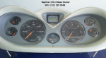
Gauges:

Gauge cluster part number is 1 911 220 934B

MCIU: Original boat wiring plugs into this new MCIU, new wiring goes from MCIU to gauge cluster connector.
The only special instruction is the extra long MICU Red/Yellow wire piggybacks to S pin on key switch, which I did.
I did all this with the battery disconnected.

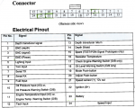
Pins

What is the bottom right blue wire on my fuse panel? Why does horn also have a red wire? The brown/green wire goes to the physical horn.
Is the red/purple wire at 9 oclock from key switch B (battery)? Seems to be. Not sure if any of this is relevant but trying to post info up front.

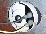
Horn

Thanks in advance.
Chris
Mercruiser 4.3L Thunderbolt V w/Alpha 1 drive
I'm not a boat guy yet, trying to get there. I can sorta use a multimeter, the basics.
I bought the boat used. Gauges have never powered up for me. Not even sure if this cluster has backlighting (cause it's never worked for me). From google, I saw that the printed circuit board in this part goes bad so I shipped it to Chicago, they fixed it (replaced chips, not gauges), bench tested it, sent it back to me. I installed back in boat. There is a new MCIU protector inline before the gauge cluster pin connector. Same result, no power. I *assume* the gauges are OK at this point. Tilt switches work, except for horn which blows the blue 15A fuse. Boat starts and runs fine.
Do both the tilt switches and gauges all get their 12V power from the pin in the cannon pug? Pin number 6?
If yes, then surely I have a ground problem. How do I test for that? Run a wire from + on battery near gauges, check for 12V on pin 1?
If no, then is my problem back at the cannon plug? Or is there an inline fuse or fuse in the fuse panel that is blown? I tested fuses in fuse panel, they are OK except for the horn.
Gauges:
Gauge cluster part number is 1 911 220 934B
MCIU: Original boat wiring plugs into this new MCIU, new wiring goes from MCIU to gauge cluster connector.
The only special instruction is the extra long MICU Red/Yellow wire piggybacks to S pin on key switch, which I did.
I did all this with the battery disconnected.
Pins
What is the bottom right blue wire on my fuse panel? Why does horn also have a red wire? The brown/green wire goes to the physical horn.
Is the red/purple wire at 9 oclock from key switch B (battery)? Seems to be. Not sure if any of this is relevant but trying to post info up front.
Horn
Thanks in advance.
Chris