monette999
Seaman Apprentice
- Joined
- Jul 8, 2011
- Messages
- 35
Dear All,
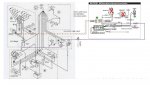
I would like to implement a Dual Ignitron System Thunderbolt IV & MSD6 AL on my boat. In case my OE System fails I have a backupsystem on
board. for the ignition advance I have purchased a extra Thunderbolt Ignnition amplifier.
I will have one dizzy and one cut out swich. Please let me know if my wiring is OK. My question is if my +12 igntion on the coil is supplying other componments
on the engine.
Sometimes the real wiring is different to the schematic.
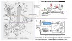
I think I need to supply the Hall Switch from the distributor with separate +12V, otherwise I have no trigger signal when I switch to MSD system.
correct?
Here a draft of my schematic diagram,
BR
Bob
I would like to implement a Dual Ignitron System Thunderbolt IV & MSD6 AL on my boat. In case my OE System fails I have a backupsystem on
board. for the ignition advance I have purchased a extra Thunderbolt Ignnition amplifier.
I will have one dizzy and one cut out swich. Please let me know if my wiring is OK. My question is if my +12 igntion on the coil is supplying other componments
on the engine.
Sometimes the real wiring is different to the schematic.
I think I need to supply the Hall Switch from the distributor with separate +12V, otherwise I have no trigger signal when I switch to MSD system.
correct?
Here a draft of my schematic diagram,
BR
Bob
Attachments
Last edited: