Electrical Issues 1970's Johnson 115

Joined
Jun 6, 2016
Messages
21
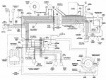
I recently acquired a Glastron boat with a 70's model Johnson 115. The first issue I noticed was the tach was not working and the battery was not being charged. After wiring inspection I found that the rectifier was corroded and bad. I purchased a new one and installed. Boat started fine and I proceeded to adjust low speed idle over the next few days. On the latest startup I noticed that it kicked itself into gear so I turned it off quickly pulled the engine cover and smelled something electrical. After inspection I noticed my clipper circuit had failed. which may or may not have caused an overvoltage to my lower unit solenoids failing the upper one. Can someone shed some light on this issue??
 

F_R

Supreme Mariner
Joined
Jul 7, 2006
Messages
28,226
The Hydro-Electric shift receives it's voltage from two sources: The alternator, and also via a blocking diode off the ignition switch. Ok, trying to make sense of what you are describing, I can imagine the clipper circuit shorting out the alternator output, thus depriving the shift switch of it's alternator-source input. BUT, it should still shift with input from the blocking diode.

I dunno, seems like you need to test ALL the diodes, including the shift diodes (monkey nutz) and the blocking diode. Nowadays, they say to throw away the clipper circuit, which I don't understand. It's purpose is to protect the ignition amplifier from spike voltages.

In any case, I can't imagine the clipper circuit damaging the shift solenoids.

Let us know what you find. We all need to learn something here.
 

F_R

Supreme Mariner
Joined
Jul 7, 2006
Messages
28,226
All diodes are tested the same way, with some sort of a continuity tester. A battery powered light will do. An analog multimeter is better (not really, but makes you feel smarter). Least favorite in my book is a digital multimeter. The test is it should pass electricity in one direction only.
 
Joined
Jun 6, 2016
Messages
21
I tested continuity on the shifting diodes last night: Negative lead on purple and green and positive lead on yellow and gray read 5.94ohms, Negative lead on purple and green and positive lead on yellow read 4.94 ohms. I was unable to read any other continuity in all other scenarios. I did test the VDC coming from the remote unit to the shifting diodes with key forward read 12VDC on green wire, When I started the engine this jumped to 130VDC. I then removed the shifting diodes and performed the same test and got 12VDC with key forward and 17VDC when started. I have not tested the blocking diode yet.
 

willvincent

Cadet
Joined
Jun 3, 2016
Messages
14
No Title

If I'm reading this schematic correctly, and it's certainly possible I'm not, it looks like it would default to forward unless the solenoid to hold it in either neutral or reverse were powered up. Could be a typo / mistake as well.

Anyway, the schematic might help you in tracing wires and such.
 

Attachments

  • photo245685.jpg
    photo245685.jpg
    359.8 KB · Views: 0

racerone

Supreme Mariner
Joined
Dec 28, 2013
Messages
38,967
Correct there is no power to solenoids when forward is selected on the control.-----Green wire get 12 volts to shift to nuetral when motor is turning.-Green and blue have 12 volts applied to shift to reverse when motor is turning.
 
Joined
Jun 6, 2016
Messages
21
Update: after tracing out the wires I found that the previous owner had taken the rectifier output wire that goes to the start solenoid off. I re-landed this wire and am getting 12vdc to the forward solenoid with key switch forward and in neutral and 14.6vdc when running. Could the output wire that had been lifted going to the battery circuit caused the overvoltage to my forward solenoid? I'm thinking of putting some in line fuses for both the forward and reverse solenoids to keep this costly issue from happening again.
 

racerone

Supreme Mariner
Joined
Dec 28, 2013
Messages
38,967
Perhaps it is the first time you have looked at a wiring diagram for this motor.-------Please look at the wiring diagram again.--3 times if you need to.----The fuse protects anything that is fed 12 volts from the battery except the starter.--Ok you do not believe this.----Remove the fuse and see if you can get 12 volts to the solenoids !
 
Joined
Jun 6, 2016
Messages
21
Wow!! Thanks for the education racerone. Sorry but I don't believe that the shift solenoids can handle current flow @ 20amps. That fuse is a main for the whole 12v circuit for a catastrophic short.
 

racerone

Supreme Mariner
Joined
Dec 28, 2013
Messages
38,967
Matthew are you well versed in ---volts / amps / ohms ?------Is this catastrophic short idea a wild guess / assumption on your part ?
 
Joined
Jun 6, 2016
Messages
21
racerone Yes I understand the basic theory of Ohm's Law. I'm just trying to figure out how I got such a high DC voltage to my drive solenoid so it does not happen again.
 

racerone

Supreme Mariner
Joined
Dec 28, 2013
Messages
38,967
Going to cost you a fuse but try this test.----Find the green shift wire at the back of the motor.------Slide the rubber boot back-------Turn ignition to " on " in the control box.----Put control in nuetral.----Touch the bare connecter to the block.------Fuse will pop but I doubt you will see anything catastrophic .---No lightning storm or thunder.
 
Top