Great White Series Motor Guide Trolling Motor -- worth fixing??

toooldtofishsoshootem

Seaman Apprentice
Joined
Sep 19, 2010
Messages
33
Hi,
I have a Motor Guide unit with partial ID information that does not run properly.
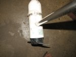
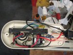
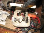
It has no proper ID information (Manufacturers decal/plate with serial/model etc) but Motor head graphics and observation provide the following: GWF 35; 12V; 41 # Thrust; 1995 Brunswick; Whisper Guide; Great White Series; On the underside of the head is a 1/4" by about 2" label with the print of: "FLY21250". The same sticker/label in found on the inside of the head cover. It is a bow mount with foot pedal which contains a 3 position toggle switch (with 3 lugs on the back), a rotary pot (with three lugs on the back) and a momentary on/off foot switch opposite the rotary speed dial.

Observations so far when unit is connected to battery; Initially slight "click" of a relay in the head; then three position switch in upper (closest to toe) position - nothing when momentary switch is activated - turning foot mounted the speed dial still nothing. Switch in center position same results. Switch in Heel (closest to heel) position motor runs at full speed regardless of position of foot controlled speed dial/pot.

Tested 3 pos switch using center lug as the common. Upper and lower positions go "off and on toggling the switch. Assume switch is OK. Momentary switch tests out OK. Speed pot again using the center lug (red wire) as the common, the top lug (black wire) shows 0 Ohms max clockwise and 27.1 Ohms max counter clockwise. Bottom lug (green wire) shows just the opposite - 0 Ohms max counter clockwise, and 27.1 Ohms when the pot is turned to max clockwise. Ohm meter is set at 200K Ohms position, and All three lugs are not connected to anything eliminating possible errant reading due to down line resistances of other parts of the circuit. Given these results, I am assuming all three components operate as designed (the Pot, the 3-way and the momentary switch).

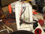
In the head there is a circuit board with a relay and other components, capacitors, resisters etc, the part number seems to be JF 157-03 - Rev "H". Wondering if this is possibly the "bad part" or if something in the wiring or the motor is faulty.

This unit may have been sold/serviced by Sears. Mercury parts/history don't seem to recognize this model but I found one reference by Sears where they did recognize this specific model number (GWF 35).

Any direction or advice would be appreciated or pricing on a JF 157-03 board.
thanks
I appreciate your help
b
 

gm280

Supreme Mariner
Joined
Jun 26, 2011
Messages
14,605
Sounds interesting. Could you post a few pictures of everything like you talked about? That way we can offer a better idea what to check and possible issues with parts. I am interesting seeing myself...
 

toooldtofishsoshootem

Seaman Apprentice
Joined
Sep 19, 2010
Messages
33
Hi GM280,
Thanks for responding - appreciate the interest.
The pics show various stages of disassembly but today I temp put the trolling motor back together. Workspace is messy and on the bench were multiple projects including a Briggs 1947 model ZZ engine that I finally could reassemble and hopefully fire up tomorrow or Sunday.

Assuming I checked out the 3 foot switches OK, that leaves the circuit board or possible one of the wires running down to the motor. However the motor does run when the 3 way switch in in the ":Hi speed position --- puzzling
Any incites appreciated. or sources for parts - not sure of pricing, consequently not sure if I want to proceed.
thanks
b
 

Attachments

  • photo333004.jpg
    photo333004.jpg
    462.3 KB · Views: 0
  • photo333005.jpg
    photo333005.jpg
    511.6 KB · Views: 1
  • photo333006.jpg
    photo333006.jpg
    570.2 KB · Views: 1
  • photo333007.jpg
    photo333007.jpg
    563.7 KB · Views: 2
  • photo333008.jpg
    photo333008.jpg
    565.2 KB · Views: 2
  • photo333009.jpg
    photo333009.jpg
    676 KB · Views: 1
  • photo333010.jpg
    photo333010.jpg
    879.4 KB · Views: 1

gm280

Supreme Mariner
Joined
Jun 26, 2011
Messages
14,605
Not being there to test anything, it looks like there are a few wires going to the motor itself. I suspect the motor windings is how it is changing the speeds. If so, you can take the red (positive) wire and the black (negative) wire and power the motor direct and it should run. Then take each of the other wires one at a time and see if you can power each individual wire itself. Leave the black wire intact going to the motor and move the red power wire to one of the other colors to see if the motor runs. Do that same test for the remaining colored wires one at a time. That way you will prove the motor windings are still good.

If you prove all the speed windings are good, then it is all in the PC board. But it also looks fairly easy to troubleshoot too. Again I am only thinking they used that PC board to apply the voltage to each wire when you select the speed at the foot control unit. I can see some very small wires coming from the foot unit to the board. So they are using the PC board as that speed switch unit instead of having large gauge wires running from the foot control.

Test the motor wire(s) and report back. That will give us a direction to go.
 

toooldtofishsoshootem

Seaman Apprentice
Joined
Sep 19, 2010
Messages
33
gm280,
Again thanks for the response-
I thought the motor speed was controlled by the infinitely variable pot in the foot pedal, that sent a variable signal to the circuit board which in turn electronically controls how much amperage is directed to the motor winding. (the speed control I didn't think was a 1-2-3-4-5 fixed speed situation, rather an infinite smoothly increase/decrease of motor speed)

RE: wires going down the tube to the motor--The blue and Green wires are of different gauges (lighter) than the Red and Black wires. Wouldn't wires to the motor winding tend to be all the same gauge and capable of carrying the same amp loads?

Another "puzzlement" to me is why the variable foot pedal pot reverses it's Ohm load depending upon which lugs you test. e.g. from my original positing: Speed pot again using the center lug (red wire) as the common, the top lug (black wire) shows 0 Ohms max clockwise and 27.1 Ohms max counter clockwise. Bottom lug (green wire) shows just the opposite - 0 Ohms max counter clockwise, and 27.1 Ohms when the pot is turned to max clockwise. Ohm meter is set at 200K Ohms position, and All three lugs are not connected to anything eliminating possible errant reading due to down line resistances of other parts of the circuit. Does this mean the Pot might be bad?

Sorry to drag this out so much - just trying to understand the original intent of the design.
b
 

gm280

Supreme Mariner
Joined
Jun 26, 2011
Messages
14,605
You could be right about variable speed unit.

When you switch the three position switch to the first position or second it does nothing right? I think that is what you said in the first post And then in the last selection the motor runs non-stop regardless of the push switch? If that is correct, then yes the variable pot does vary the speed to the controller board as you thought. Why there is three positions could only be that in one position, you have variable speed with push control, second position variable speed without push control, and third position fixed speed with out push control. Again not being there, just speculation.

So that points to that controller board. I searched for it on line and seems they don't sell it separately. But if you can move thing around, where the parts on that PC board are seen, you could possible replace the part that controls the variable speed. Just need to see the board better.

If you like this TM, I would certainly repair it and use it. It really doesn't look like it was abused at all. Are you the original purchaser? JMHO
 

toooldtofishsoshootem

Seaman Apprentice
Joined
Sep 19, 2010
Messages
33
gm280,
The motor came to me from a neighbor ($00.00). He bought a boat from someone, this motor came with it, don't know if he knew is it ran or not but he did not want it consequently I ended up with it. I have no clue what its history might be. He thought I could use it on my jon boat. two years or so have gone buy, and I finally started to look at it about 1-2 weeks ago. found out it doesn't work as designed, AND once I thought seriously about it would not be very useful mounted on a little 14" jon boat.

The 3 position switch according to the "owners Manuals" of similar models is: UP-(towards the toe of the pedal) is termed "constant on", middle position is designated as the "momentary" position, and the down position (closest to the heel of the foot pedal is termed the High speed position - no speed control but activated with the off/on foot switch on the right side of the pedal.

My Briggs ZZ project is coming to a close, I will disassemble the head and try to get better pics of the control board although is it small (about 2 1/2" X 3') and has many very small resisters, capacitors, diodes - what ever in addition to a larger capacitor and a relay about 1" square. It would be a #*@#&#^&@# to try and de-solder some of the components to test and replace without damaging the printed circuit board. Plus I have no way of knowing what to test or what values would be significant.

Over the next couple of days, I will snap 2-3 more pics of the board itself as best I can without unplugging all the wires that connect to the board from elsewhere in the motor.

BTW, is there a way to have iboats forum automatically notify me (e-mail) when a post/reply is made to a thread I am involved with? As it stands now, I need to log in when I remember to, and re-find my question just to see if there is a reply or new information.

appreciate your help
b
 

gm280

Supreme Mariner
Joined
Jun 26, 2011
Messages
14,605
gm280,
The motor came to me from a neighbor ($00.00). He bought a boat from someone, this motor came with it, don't know if he knew is it ran or not but he did not want it consequently I ended up with it. I have no clue what its history might be. He thought I could use it on my jon boat. two years or so have gone buy, and I finally started to look at it about 1-2 weeks ago. found out it doesn't work as designed, AND once I thought seriously about it would not be very useful mounted on a little 14" jon boat.

The 3 position switch according to the "owners Manuals" of similar models is: UP-(towards the toe of the pedal) is termed "constant on", middle position is designated as the "momentary" position, and the down position (closest to the heel of the foot pedal is termed the High speed position - no speed control but activated with the off/on foot switch on the right side of the pedal.

My Briggs ZZ project is coming to a close, I will disassemble the head and try to get better pics of the control board although is it small (about 2 1/2" X 3') and has many very small resisters, capacitors, diodes - what ever in addition to a larger capacitor and a relay about 1" square. It would be a #*@#&#^&@# to try and de-solder some of the components to test and replace without damaging the printed circuit board. Plus I have no way of knowing what to test or what values would be significant.

Over the next couple of days, I will snap 2-3 more pics of the board itself as best I can without unplugging all the wires that connect to the board from elsewhere in the motor.

BTW, is there a way to have iboats forum automatically notify me (e-mail) when a post/reply is made to a thread I am involved with? As it stands now, I need to log in when I remember to, and re-find my question just to see if there is a reply or new information.

appreciate your help
b

I just posted your last post so you should be alerted to my reply when you log in. Any time you want to include or get attention to your comment, you can use their login name ie.. gm280 would alert me if you posted that. I can do the same with you as toooldtofishsoshootem That should alert you if I post that. The alert is shown under your monitor on the right hand side of the top next to the shopping cart icon. If you see any number there, click on it and it will take you to the message section for you to click on any message and go to that post. Hope that helps...

As for the TM, if the variable pot changes (or supposed to change) the speed, that means there has to be some electronic circuit to allow that control of the current. Once I get a better view of the circuit board I can possible figure out what component that is.

If you want to include anybody's comment in your reply, click on the lower right hand side of the comment and click on the Quote name.
 

gm280

Supreme Mariner
Joined
Jun 26, 2011
Messages
14,605
Thanks, I'll post some pics as soon as I take them.
b

I tried today a few times to research your TM and the circuit board and even the circuit schematic diagram, but I didn't find what I was looking for. Could be some parts are still available for that model, but I didn't get to find your exact model to know...
 

toooldtofishsoshootem

Seaman Apprentice
Joined
Sep 19, 2010
Messages
33
Hi gm280
Good and surprising news. I was going to disassemble the head one more time to try and expose the circuit board for pics as we discussed. For whatever reason, i went thru each connection, again for the 3rd time, wiggled the connector, wiggled the spad lugs on the switches and board, etc after I used almost a whole can of break clean fluid on all the switches, common connection posts, circuit board, etc and checked and tightened as necessary all the slide on fastners that slide over the spade lugs and literally re bent all the lugs coming out of each switch. I also put my backup trolling motor battery in the mix rather than my primary one -0--shot story long everything worked as designed. What changed or what the original problem was is still a mystery. As it was running in my last test, I wiggled each wire at its solder joint, and wiggled each lug on each switch, kicked the motor a couple of times :joyous: nothing faltered or hick-upped. I replace the pilot bulb in the head to illuminate the directional arrow and closed it up. One of those times you just smile and move on.

Thanks gm280, appreciate you following thru and time for helping out. I joined a similar forum at MarineEngine.com and never got one response from anyone. Your responses and over the shoulder help was good to have.

b
 

gm280

Supreme Mariner
Joined
Jun 26, 2011
Messages
14,605
Well that IS great news. Probably was some iffy contact maybe it the switches or who knows where. But since you went over everything and it is now working, YOU fixed it. I say, enjoy it and very happy boating. :thumb::thumb:
 
Top