Need help if anyone can. Boat is a late 70s Mercruiser 165 equipped Glastron. It had the trim sending unit and trim limit switch both fried. Their pigtails gone at the transom.
Inside the boat found the wire pair that goes to the trim limit switch. They're seen in one of the pictures. No certainty on the pair for the trim sending unit though.
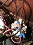
In the rear of the boat coming back with the main harness I found the pair of wires that can be seen in what appear to be two shades of blue. They'd been cut off at the point you now see them stripped back a bit. I was hoping they went to the trim sender connections for no other reason than they were the only unused pair in the back of the boat.
The other picture shows the back of the trim gauge. Using an ohm meter both of the wires from that wire pair in question show continuity to every post on the back of the trim gauge. I then unhooked the lighter purple/violet/pink/whatever-color-it-is wire from the pictured bottom left of the trim and checked for continuity again. Once again both wires at the rear of the boat showed continuity to everything. Both to the now disconnected wire and to the ground and other post on the back of the trim gauge.
Not sure what I expected. But that wasn't it.
First off can anyone confirm that this pair in the back should go to the trim sender. I have two different schematics in hand now and neither are complete for that connection.
If that is or isn't the pair does the continuity to and through the gauge sound right. I was trying to think of it like a gas gauge and it's not behaving that way. Even wondering now if the gauge failed sometime and someone couldn't sort it out so just cut off the sender pair as a way to give up.
I realize the wire pair in the back doesn't color match the contacts on the back of the trim gauge. I can't find a splice along the harness's run up the right side of the boat. Perhaps it's changing colors at the connectors under the dash. This I can't say right now.
With the information at hand if anyone can offer an insight it'd be appreciated. Doing this so far with the battery unhooked. I do have another trim gauge here that could be swapped in if the descriptions make the currently installed piece sound defective. Also don't mind running another wire pair back to the sending unit's connectors if I knew for sure what/where they'd connect to.
Thanks.
Inside the boat found the wire pair that goes to the trim limit switch. They're seen in one of the pictures. No certainty on the pair for the trim sending unit though.
In the rear of the boat coming back with the main harness I found the pair of wires that can be seen in what appear to be two shades of blue. They'd been cut off at the point you now see them stripped back a bit. I was hoping they went to the trim sender connections for no other reason than they were the only unused pair in the back of the boat.
The other picture shows the back of the trim gauge. Using an ohm meter both of the wires from that wire pair in question show continuity to every post on the back of the trim gauge. I then unhooked the lighter purple/violet/pink/whatever-color-it-is wire from the pictured bottom left of the trim and checked for continuity again. Once again both wires at the rear of the boat showed continuity to everything. Both to the now disconnected wire and to the ground and other post on the back of the trim gauge.
Not sure what I expected. But that wasn't it.
First off can anyone confirm that this pair in the back should go to the trim sender. I have two different schematics in hand now and neither are complete for that connection.
If that is or isn't the pair does the continuity to and through the gauge sound right. I was trying to think of it like a gas gauge and it's not behaving that way. Even wondering now if the gauge failed sometime and someone couldn't sort it out so just cut off the sender pair as a way to give up.
I realize the wire pair in the back doesn't color match the contacts on the back of the trim gauge. I can't find a splice along the harness's run up the right side of the boat. Perhaps it's changing colors at the connectors under the dash. This I can't say right now.
With the information at hand if anyone can offer an insight it'd be appreciated. Doing this so far with the battery unhooked. I do have another trim gauge here that could be swapped in if the descriptions make the currently installed piece sound defective. Also don't mind running another wire pair back to the sending unit's connectors if I knew for sure what/where they'd connect to.
Thanks.