Help with parts location and distributor travel

hartleck

Seaman
Joined
Mar 14, 2010
Messages
54
I have two parts here that I can't seem to locate where they attach they are a part of the control cable linkage setup if I am correct. I have looked at diagrams but they just show the exploded view of parts and I have no pics of their location. They are # 50 and # 51 in the exploded parts view. (see Pics). also when my cables are connected there is very little travel in the distributor. Is that normal?
 

Attachments

  • 20.jpg
    20.jpg
    25.5 KB · Views: 0
  • 25.jpg
    25.jpg
    12.5 KB · Views: 0
  • 23.jpg
    23.jpg
    14.8 KB · Views: 0

Chris1956

Supreme Mariner
Joined
Mar 25, 2004
Messages
28,136
Re: Help with parts location and distributor travel

Those parts go on the shift slide. The white "bow tie" sits over the bolt in the shift slider. The aluminum "acorn" sits on the bolt as well. The shift cable is held in place on the shift slider pin (in front of bolt) by the round protrusion on the underside of the acorn. The nut is snugged down to keep the shift cable in place.

The distributor should rotate enough to advance the saprt to 21* BTDC. That is less than a 1/4 turn, if I remember correctly.
 

Chris1956

Supreme Mariner
Joined
Mar 25, 2004
Messages
28,136
Re: Help with parts location and distributor travel

That is "advance the spark to 21* BTDC". Sorry for the typo
 

hartleck

Seaman
Joined
Mar 14, 2010
Messages
54
Re: Help with parts location and distributor travel

Thanks Chris, now to the next part, I have replaced the control cables, spark plug & coil wires clips and boots, external harness as well as check internal harness for cracked or otherwise damaged wires and replaced those necessary. The rotor shaft has been replaced, plugs are good, compression is good, fuel line and bulb replaced carbs cleaned, not rebuilt. Vacuum elbow on the distributor housing replaced. Fresh gas and additives, distributor cap checked and cleaned. I have a good strong turn over when key turned but no fire to plugs. I do not have a manual but have read as much as I can find on ignitions of that era. 1971 Thunderbolt 800.

I also can not determine if the electric choke button on the remote works or not. When I replaced the harness I did not splice but rather de-soldered and re-soldered the wires inside the remote box and double checked for cold joints. I know there are other things to check but not sure what.
 

Moody Blue

Captain
Joined
May 24, 2004
Messages
3,136
Re: Help with parts location and distributor travel

Wow Hartleck, you've done alot of work on that motor. Best way to get to know your motor.

These two conditions that must be met in order to obtain a spark from the switchbox.
1) +12V at the RED terminal (starter side of switchbox) - this is present all the time
2) +12V at the WHITE terminal (starter side of switchbox) - this is present only when the ignition key is turned to START or RUN

If the trigger circuit and coil are in good operating condition, and the battery is fully charged, and the above conditions are met, then you should have spark to the plugs. The next important thing to determine is if the spark is occurring at the proper point in time. That's a topic for discussion later.

As for the choke, you will be able to hear it activate when you push the choke button. There will be a loud CLICK. The choke is only activated while the choke button is held down. With the cowling removed you will be able to see the choke linkage activate when the button is pressed.

Here is a link to a wiring diagram for your motor

http://www.maxrules.com/oldmercs/Wiring/1966ona/30.gif
 

hartleck

Seaman
Joined
Mar 14, 2010
Messages
54
Re: Help with parts location and distributor travel

....These two conditions that must be met in order to obtain a spark from the switchbox.
1) +12V at the RED terminal (starter side of switchbox) - this is present all the time
2) +12V at the WHITE terminal (starter side of switchbox) - this is present only when the ignition key is turned to START or RUN

If the trigger circuit and coil are in good operating condition, and the battery is fully charged, and the above conditions are met, then you should have spark to the plugs. ....Here is a link to a wiring diagram for your motor

http://www.maxrules.com/oldmercs/Wiring/1966ona/30.gif
Thanks Moody Blue but I am a newbie at this and need some clairification on what and where the switchbox is. A;so, how would I check the trigger circut and coil? Sorry for having to ask. I've worked on cars extensivly years ago but never boats.
 

Moody Blue

Captain
Joined
May 24, 2004
Messages
3,136
Re: Help with parts location and distributor travel

The switchbox is the electrical "brain" of the ignition system. It is the flat rectangular box (about 6" x 6" x 2") mounted in front of the carbs. The trigger wires from the distributor connect to the port side of the switchbox and the power & coil wires connect to the starboard side of the switchbox. Refer to the link I sent you for clarification.

For now, assume the coil is good. Rarely do they become faulty. Not familiar with a test procedure for the trigger circuit other than by method of elimination. Others may be able to offer a specific test procedure. Below is a link to test procedures for you ignition system called a Battery type CD ignition system. Refer to page 38 - 39.

http://www.maxrules.com/cdi/TroubleshootingGuide.pdf

This will allow you to test the switchbox independently of the rest of the system.
 

hartleck

Seaman
Joined
Mar 14, 2010
Messages
54

Attachments

  • 2011-03-13_13-31-13_802.jpg
    2011-03-13_13-31-13_802.jpg
    142.8 KB · Views: 0
  • 2011-03-13_13-31-36_885.jpg
    2011-03-13_13-31-36_885.jpg
    142.2 KB · Views: 0

Moody Blue

Captain
Joined
May 24, 2004
Messages
3,136
Re: Help with parts location and distributor travel

Seems you may have a unique switchbox. Lucky you. Trying to make out the details in the photos. First photo is of the switchbox (4 terminals only) and the second photo is of the rectifier (3 terminals). Is that correct?

This is most likely the wiring diagram for your motor.

http://www.maxrules.com/oldmercs/Wiring/1966ona/31.jpg

Post back with a motor S/N if you can find one. It's located on the tilt tube of the transom clamp.

One thing I don't see in the photos is the mercury switch (engine tilt kill switch). If it is still connected, it may be the cause of the no-spark condition. If the mercury switch is shorted/defective, it will disable the ignition system.

In the second photo, I see the choke plunger hanging down, out of place. That is the reason you can't test your electric choke operation.
 

Gomer50

Chief Petty Officer
Joined
Sep 5, 2009
Messages
507
Re: Help with parts location and distributor travel

These are the instuctions to test your switchbox.
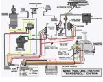
This test is for the 332-2986 switchbox used from 1967-1978 on all the inlines.

This test assumes your coil is good (problems with CDI coils are rare).

DISCONNECT BATTERY

1. Turn off ignition;

2. Disconnect all 3 distributor wires on the Port side of the switchbox (and the ?mercury switch? if present);

3. Remove the High Voltage lead from the ign coil to the center of the dist. cap (remember it unplugs from the coil and unscrews from the cap);

4. Reconnect the H.V. lead to the COIL only;

5. Position the free end of the HV lead approx. 3/8" from ground (block, shrouds etc), and find a way to hold it there;

6. Jumper the brown and white terminals on the distributor side of the switchbox to each other.

RECONNECT BATTERY

7. Check that you have +12V at the red terminal (even with the ign off);

8. Turn on ignition and verify +12V at the white terminal (same side as the red terminal);

9. Ground the black terminal on the distributor side of the switchbox - this should cause a spark each time you touch ground.

If you get spark with the distributor bypassed, and it won't fire with the distributor connected, the trigger is bad and the entire distributor housing assy must be replaced.

If you get no spark using the test, the switchbox is probably bad. In that case, be sure to check for correct power on the switchbox, check all connections, and check the coil's resistance to make sure it's OK."
Also make sure your neutral safety switch in your remote control box is in working condition.

.:cool:
 

Gomer50

Chief Petty Officer
Joined
Sep 5, 2009
Messages
507
Re: Help with parts location and distributor travel

One more thing too check is inside the distributor cap center is a carbon thingy with a spring make its good.
 

hartleck

Seaman
Joined
Mar 14, 2010
Messages
54
Re: Help with parts location and distributor travel

Seems you may have a unique switchbox. Lucky you. Trying to make out the details in the photos. First photo is of the switchbox (4 terminals only) and the second photo is of the rectifier (3 terminals). Is that correct?

This is most likely the wiring diagram for your motor.

http://www.maxrules.com/oldmercs/Wiring/1966ona/31.jpg

Post back with a motor S/N if you can find one. It's located on the tilt tube of the transom clamp.

One thing I don't see in the photos is the mercury switch (engine tilt kill switch). If it is still connected, it may be the cause of the no-spark condition. If the mercury switch is shorted/defective, it will disable the ignition system.

In the second photo, I see the choke plunger hanging down, out of place. That is the reason you can't test your electric choke operation.
Please define "Lucky Me"...is that a good thing or a not so good thing? Thanks for the correct diagram. You are correct about your assessment of the pictures. I don't know what the mercury kill switch looks like or where it should be. I didn't know the thing hanging down was related to the choke. Is there any pictures that could show me how to fix it? I really appreciate you taking your time to help me on this.

One more thing too check is inside the distributor cap center is a carbon thingy with a spring make its good.
I am familiar with it is looks like the brush on an electric motor. It showed no signs of wear but is there anything else to look for on it? Thanks for your help.
 

Gomer50

Chief Petty Officer
Joined
Sep 5, 2009
Messages
507
Re: Help with parts location and distributor travel

Looking at the choke piston thats hanging there in your pictures.Take a look right above that in between the starter and the top of the carb. you will see the other part of the choke assembly,there should also be a gray wire hooked up to it.Slide the choke piston inside the solenoid.Turn your key on your control box to the run position and push the choke button,you should here a click back at the motor and if positioned right you could see if the choke flaps on the carbs close.
 

Attachments

  • choke.JPG
    choke.JPG
    18.2 KB · Views: 0
  • choke 2.JPG
    choke 2.JPG
    56.4 KB · Views: 0

hartleck

Seaman
Joined
Mar 14, 2010
Messages
54
Re: Help with parts location and distributor travel

Looking at the choke piston thats hanging there in your pictures.Take a look right above that in between the starter and the top of the carb. you will see the other part of the choke assembly,there should also be a gray wire hooked up to it.Slide the choke piston inside the solenoid.Turn your key on your control box to the run position and push the choke button,you should here a click back at the motor and if positioned right you could see if the choke flaps on the carbs close.
I assembled the choke as you showed here and it works perfectly. One down and on to the next step. Thanks.
 

merc850

Commander
Joined
Jul 7, 2010
Messages
2,050
Re: Help with parts location and distributor travel

The wires from the trigger should be in a grommet to prevent shorting and it looks to me that the trigger assem. might be a problem itself.
 

Gomer50

Chief Petty Officer
Joined
Sep 5, 2009
Messages
507
Re: Help with parts location and distributor travel

I have been looking at your pics again,and have noticed that you have the switchbox mounted the wrong way the 4 conectors should be on side where the distributor should be and the 3 connectors should be on the distributor side.Therefore your wiring is not on the correct post.I will put up some pics to maybe show the correct wiring.As example your coil wire should be on the bottom post the way you have mounted your switchbox.I hope I am not confusing you.And I hope you didnt burn up that swithbox the way its hooked up.
 

Attachments

  • wiring diagram.jpg
    wiring diagram.jpg
    21.3 KB · Views: 0
  • Switchbox2.JPG
    Switchbox2.JPG
    35.3 KB · Views: 0
  • Switchbox.JPG
    Switchbox.JPG
    45.3 KB · Views: 0

hartleck

Seaman
Joined
Mar 14, 2010
Messages
54
Re: Help with parts location and distributor travel

I have been looking at your pics again,and have noticed that you have the switchbox mounted the wrong way the 4 conectors should be on side where the distributor should be and the 3 connectors should be on the distributor side.Therefore your wiring is not on the correct post.I will put up some pics to maybe show the correct wiring.As example your coil wire should be on the bottom post the way you have mounted your switchbox.I hope I am not confusing you.And I hope you didnt burn up that swithbox the way its hooked up.
I followed your step by step troubleshooting guide and it does not look good by that standard; however, the switchbox I have is not the P/N or type you are talking about. I only have contacts on the distributor side and none on the other side. From what I can find out it was an early box used that year and changed out after a small number of engines were assembled. I don't know if the guide you gave me is applicable. I also have no mercury switch. Do I need one? Moody Blue posted the correct link for the diagram I need uo above.
 

Chris1956

Supreme Mariner
Joined
Mar 25, 2004
Messages
28,136
Re: Help with parts location and distributor travel

You do not need the Mercury switch, but do not ground the blue wire, as this will kill spark. Is that some sort of points/condenser setup in the distributor?
 

Moody Blue

Captain
Joined
May 24, 2004
Messages
3,136
Re: Help with parts location and distributor travel

Gomer50, the switchbox he has is not the typical type found on most of these in-lines. His is a rare breed. His photos show a different switchbox and an original 3 terminal rectifier. The switchbox is not installed backwards.

Hartleck, the test procedure is not applicable to your switchbox, but should be able to figure out a way to test it. Will try to get back to you tomorrow.

Good news on getting your choke working. A step in the right direction.
 
Top