High level wiring diagram - review

texas_bayfisher

Recruit
Joined
Mar 3, 2019
Messages
5
Hello all,
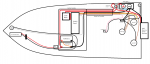
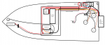
New here, just picked up a 2005 20 ft bay boat for fishing the Texas coast (inshore only) and freshwater lakes. I am reworking the wiring since the previous owner left a bit of a rats nest, and I'd like to add some features/make it mine - a switch to use one of my trolling motor batteries as a backup starting battery, replace a bunch of ugly splices with terminal blocks, more clean/organized wiring, add fuses where previous owner didnt have any, utilize a fuse box, etc. I've drawn up a high level schematic and just wanted to some of you experts' thoughts and suggestions - and to make sure I didnt mess up anything!

I plan on having all three batteries be AGM with sufficient CCA for starting
 

Attachments

  • photo308694.png
    photo308694.png
    26.5 KB · Views: 0
Last edited by a moderator:

Silvertip

Supreme Mariner
Joined
Sep 22, 2003
Messages
28,771
You do realize AGM #1 will never see a charge from the engine. I would also suggest that you be very thorough in labeling all of the wiring because a miss step in that process can apply 24 volts all 12 volt devices leaving you with an expensive mess. What you are proposing will work but it leaves you wide open for the problem I just pointed out.
 

The Force power

Commander
Joined
Feb 3, 2019
Messages
2,351
in addition of Silvertip advice

In this drawing;
the 12V. coming of the Engine will go straight to the 24V. trolling- motor and not through the batteries
(path of least resistance)

the pos.wire from the engine-motor should have a directional diode before it reached the pos. terminal from AMG#2
so that no 24v. that has been made/stored can't flow back to the 12v.side

in this set-up the AWG#1 will not be able to start the motor
 

texas_bayfisher

Recruit
Joined
Mar 3, 2019
Messages
5
Thanks for the feedback - very much appreciated.

I am indeed aware that the battery will not charge AGM #1. The intent (hope) is to never have to use AGM #2 to start the engine. The option to switch to AGM#2 is a worst-case backup plan to keep from getting stranded/towed. AGMs #1 and #2 will normally be charged using a separate charger, not shown in the drawing.

"In this drawing;
the 12V. coming of the Engine will go straight to the 24V. trolling- motor and not through the batteries
(path of least resistance)"

Thanks for the heads up. I don't think it will an issue so long as I am diligent about keeping the trolling motor unplugged when not in use, and having the motor off when I am trolling (this is only if the switch is ever set to select AGM#2 as the starting battery, which hopefully, it wont be).

"the pos.wire from the engine-motor should have a directional diode before it reached the pos. terminal from AMG#2
so that no 24v. that has been made/stored can't flow back to the 12v.side"

Can you elaborate on how this can happen? The motor is connected to the terminals of AGM#2 - how could these terminals see 24 V?

Thanks!
 

texas_bayfisher

Recruit
Joined
Mar 3, 2019
Messages
5
Also, what are people's thoughts on running AGM #1&2 in parallel instead of in series? My trolling motor can use 12v or 24v. This way, there is no risk of accidentally putting 24v on any other load and I double my amp-hour capacity to the trolling motor. Thoughts?
 
Top