dsweet2010
Cadet
- Joined
- Jul 30, 2017
- Messages
- 16
I have a 1974 Johnson 70hp with a believed to be bad rectifier. My question is, and I use a 3-wire Kohler lawn mower regulregulatoro the same thing? Considering I tried unsuccessfully I will assume my answer will be no. Appears to be the same concept however the diode check with my multimeter did not show current flow in either direction .
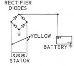
This this thing has me seriously stumped . Upon finding a bad burnt red wire on my old rectifier and having no charging, I automatically assumed to have a bad rectifier . I posted on here and asked if I could use a 4-wire that I had at home in place of a 3 wire on my motor. I was told yes so I taped up the remaining yellow and blue wire and installed it and still did not charge .I then bought a new 3 wire unit from the local Marine store and and did get 13 volts charging temporarily. I then checked all of my accessories and proceeded to flip my battery selector to both and just the other battery to test it . Somewhere in that process, I again lost charging all together. I do not have a DVA meter . I have done numerous checks for AC and DC with my multimeter though . All of my rectifiers and stator check for correct ohms and no short to grounds. With the motor running and the red wire unplugged coming out of my rectifier I show 9 9 AC volts from each stator lead and 20 volts ac between both yellow stator wires. The red wire coming from rectifier shows 22 DC volts .Whenever I hook up the red wire back to the terminal, it reads completely different. With everything hooked back up I then show 20 ac volts from only one stator wire to ground and no voltage from the other . The red wire output shows only the 12 volt battery voltage. I don't know why I get completely correct readings while unhooked but then everything reads wacko when hooked up . My first thinking's want to be that I fried the new rectifier that did temporarily work by switching the battery selector with the motor running . It is also hard to believe that I can be holding three rectifiers that test good on diode checks on my meter and show correct resistance with no shorts and still not have charging from any of them. Thoughts???
This this thing has me seriously stumped . Upon finding a bad burnt red wire on my old rectifier and having no charging, I automatically assumed to have a bad rectifier . I posted on here and asked if I could use a 4-wire that I had at home in place of a 3 wire on my motor. I was told yes so I taped up the remaining yellow and blue wire and installed it and still did not charge .I then bought a new 3 wire unit from the local Marine store and and did get 13 volts charging temporarily. I then checked all of my accessories and proceeded to flip my battery selector to both and just the other battery to test it . Somewhere in that process, I again lost charging all together. I do not have a DVA meter . I have done numerous checks for AC and DC with my multimeter though . All of my rectifiers and stator check for correct ohms and no short to grounds. With the motor running and the red wire unplugged coming out of my rectifier I show 9 9 AC volts from each stator lead and 20 volts ac between both yellow stator wires. The red wire coming from rectifier shows 22 DC volts .Whenever I hook up the red wire back to the terminal, it reads completely different. With everything hooked back up I then show 20 ac volts from only one stator wire to ground and no voltage from the other . The red wire output shows only the 12 volt battery voltage. I don't know why I get completely correct readings while unhooked but then everything reads wacko when hooked up . My first thinking's want to be that I fried the new rectifier that did temporarily work by switching the battery selector with the motor running . It is also hard to believe that I can be holding three rectifiers that test good on diode checks on my meter and show correct resistance with no shorts and still not have charging from any of them. Thoughts???