L6 Mercruiser simplified engine wiring

ttownthomas

Petty Officer 2nd Class
Joined
Jun 7, 2019
Messages
199
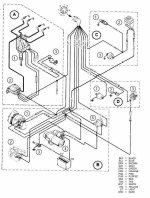
I'm planning a complete re-wire on my 25 Bertram. It has Twin Mercruiser L6's and Ill be clean sheeting the electrical system since all wiring has been removed from the boat. the original harnesses have a 6-ish gauge power wire that ran to an ammeter for each engine and then the house loads and their fuse blocks tied into this larger wire. Thus the house loads were generally split between the 2 batteries. In my case I plan to have a dedicated house battery and thus I will not need this larger wire to run to the panel. I would like to eliminate it and probably will build my own harness. Re-writing/drawing helps me learn so I have re-drawn the wiring diagram (with some slight modifications) from the FSM but was hoping the forum could look to see what I am missing on this diagram.

51006478368_b97a82e332_c.jpg


What type of battery switches will I want with 3 batteries? Where should circuit breakers go? Should I run the trim pumps off the starting batteries?
 

Scott Danforth

Grumpy Vintage Moderator still playing with boats
Staff member
Joined
Jul 23, 2011
Messages
50,370
do yourself a favor and use todays ABYC wiring codes (in the electrical forum)
 

Scott Danforth

Grumpy Vintage Moderator still playing with boats
Staff member
Joined
Jul 23, 2011
Messages
50,370
by the way, if you re-organize the wiring and lay the parts out exactly like they are in the boat. you will realize you have the same number of wires and connections as the factory harness. you have simply overlooked the two connectors in the gunwale harness. the one back by the motor and the one near the controls.
 

ttownthomas

Petty Officer 2nd Class
Joined
Jun 7, 2019
Messages
199
I thought I left out only the large red 12v wire and all the trim pump wiring
 

ttownthomas

Petty Officer 2nd Class
Joined
Jun 7, 2019
Messages
199
I thought I left out only the large red 12v wire and all the trim pump wiring
Oh I see what you mean. My boat only had one connector at the engine but there is also a 40 amp breaker on the removed large gauge wire.
 

alldodge

Moderator
Staff member
Joined
Mar 8, 2009
Messages
42,662
If you go ABYC then use 3 pole key switch (Bat, Run, Start)
In drawing above it shows Acc going to 2 gauges and the ALT. These should go to the run circuit even if you rewire with 4 pole key.
 

alldodge

Moderator
Staff member
Joined
Mar 8, 2009
Messages
42,662
The ALT should have 4 connections
Ground - Black
Output - Orange
Sense - Red/purple from 50 amp breaker
Excite - Purple from key3_0L wiring Diag.jpg

This is a 3.0 using EST distributor but other then that the wiring will be the same
 

alldodge

Moderator
Staff member
Joined
Mar 8, 2009
Messages
42,662
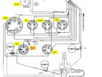
This is the helm wiring using the standard 10 pin harness
Note all gauges tie into the Purple

Wiring Helm.jpg
 

ttownthomas

Petty Officer 2nd Class
Joined
Jun 7, 2019
Messages
199
I have been studying and I think this has all the AYBC colors and standards but I'm still not sure this is right. And if it is right schematically, what wire color should I be using for the harness side of the resistance wire shown here in red? should it be purple? My alternator, by the way, only has 2 posts. Batt and ground

51012555803_67d369f41a_c.jpg
 
Last edited:

alldodge

Moderator
Staff member
Joined
Mar 8, 2009
Messages
42,662
The wiring isn't correct in design nor color for AYBC
The red from the run circuit is connected correctly, but uses a white resistance wire. This in it self is ok, but should be purple or go to a ballast resistor, unless a resistance wire is used

There is no ALT output connection back to the + side of the battery

All grounds should be spliced together and go back to the connector except the black going to the - side of coil

There is no Red/purple after the main breaker going to the connector.

Merc Color Codes.png
 

ttownthomas

Petty Officer 2nd Class
Joined
Jun 7, 2019
Messages
199
Sorry for being so slow....Did you mean it should look Like this?

51012995633_72f976a2ca_c.jpg
 
Last edited:

alldodge

Moderator
Staff member
Joined
Mar 8, 2009
Messages
42,662
Just noticed you removed the purple on the ALT and added a wire to the bat

What you have will work but will need to put the purple wire back to the ALT. In fact the ALT needs 4 wires total
Orange - output to bat
Purple - Excite which turns the ALT on from the key
Red/purple - 12V full time from the motor main breaker
Black - case ground

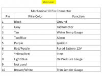
I'm unable to read the pins on the connector so not sure if pin out is correct.

10 pin Connector.jpg
 
Top