Mercruiser 140 1975 Wiring Issue

Joined
Jul 24, 2019
Messages
11
Hello fellow Boaters!
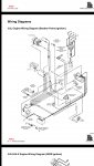
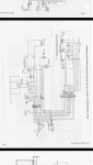
I am seeking assistance trying to figure out the wiring on my engine. I have installed a newer model engine into my Glastron Bayflite 1973. The colour coding is different in the harness I have figured out most of the wires but can't figure out where to connect the RED/WHITE wire from alternator.. I have a 3 terminal key switch. 2 wires coming off alternator. The ignition system works at correct voltage, oil press, temp gauge work. Tach is no good and I have disconnected. Do I need to replace my key switch to a 4 term key? I have worked countless hours on this please please help! Thank you very much for any guidance!!
 

Attachments

  • photo317902.png
    photo317902.png
    511.1 KB · Views: 0
  • photo317903.png
    photo317903.png
    749.5 KB · Views: 0
Joined
Jul 24, 2019
Messages
11
Sorry for the rough explanation! This site has been amazing so far.. to clarify I am connecting the engine wiring harness to existing harness to dash and I am struggling with the Red / white wire.. any help is appreciated!
 

Bt Doctur

Supreme Mariner
Joined
Aug 29, 2004
Messages
19,453
If all systems are good, "charging voltage" then you dont need the Red/White to go anywhere. Your new alt should be self contained and has no need for a external regulator
The 2 wires on the alt should be "sense" constant 12v and "excite" a switched 12 v
 
Joined
Jul 24, 2019
Messages
11
Much obliged Sir!! Thank you very much for the reply!! I will double check the voltage readings all around and report back. At first I had ignition issues because of incorrect connections too many volts to coil would overheat. I still have the old points and might replace to petronix. Have you encountered this issue before? I will remove and tape up the red white wire. So the previous engine must have had an external regulator eh? Very grateful for the priceless veteran knowledge!!
 
Joined
Jul 24, 2019
Messages
11
Ok so, I'm back from the boat! Thank you again and Sorry for the confusion earlier! I am still having problems with the wiring harness connections on my family's old glastron. As I struggled to explain earlier, I have recently replaced engine from a 1973 model 140 to a 1977 140 ser# starts with 44. Upon installation wiring harness plugs are completely different so I got a short length of harness with male plug and began to trace and connect wires according to diamgrams and following from dash to plug. I can not figure out where to crimp/connect the larger Red/white wire from engine to dash. The red white wire comes from one of two alternator terminals via continuity test to #4 pin is a larger gauge. Two other large gauge wires are red and black at the harnes plug total 3 larger gauge wires. Key switch has 3 terminals. Last test run, she starts and runs decently, I think charging is a bit lower to battery (13.2 before it was around 14).. seems to run with normal range of voltage to coil.. avg 10V. But this time engine would Not shut off with key! I could not stop the engine during docking!! I tried disconnecting battery but she kept running so I admit panicked and popped coil wire off to stop.. S.O.S! I have my idle screw set too high most likely but I think this wire must go somewhere. Please excuse my lack of proper terminology! Any ideas are greatly appreciated!! I will go and make a proper list of the connections to provide more info! Including exact ser. # of engine! Thank you for your time!
 
Joined
Jul 24, 2019
Messages
11
Also I think I have the wrong wiring diagram. I think I am I need of service manual number 3 for the serial number starting with 44. This may provide me with the answers I need! Thank you again!
 

achris

More fish than mountain goat
Joined
May 19, 2004
Messages
27,468
It sounds like you are trying to connect a 'voltmeter' engine harness to an 'ammeter' instrument harness.

If that's the case, then it's not as easy as it looks... I do remember helping someone else about a year or 2 ago do the same thing... I'm currently away from home and don't have access to the resources I need for this particular question, if you can wait for about 4 weeks, I can step you through how to do it...

Chris....
 
Joined
Jul 24, 2019
Messages
11
Thank you for the reply Chris! This is extremely helpful! I think we have identified the issue! Very kind of you to offer further assistance! Just very eager to get hear 100% done this season for the family. I have been digging in the archives and found your work from a few years back! The colours and diagram attached are mostly a match to my engine wiring harness and has correct number of alternator terminals. I can see the changes you have made as well. Is this what you were referring to? I will compare the updated/changed instrument panel diagram you provided to the existing dashboard. I think it may already be set up like this from previous repairs because there is no "red/white" wire to dash as is. I will take pictures and post for further info.. Maybe I just have to run the redwhite to slave solenoid as you have previously suggested? Any further help is Greatly appreciated once again!!
 
Joined
Jul 24, 2019
Messages
11
Hello everyone! All the help has great so far I appreciate the wisdom! After studying the ammeter/voltmeter different circuits in the 70s I think I have figured out how to wire it up thanks to Chris. I finally found the correct wiring diagrams for serial number and I have connected the alternator output wire red-white to the positive connection on slave solenoid. In the diagrams Chris provided my dash is already set up for a voltmeter circuit. I have not been able to water test yet. Does anyone else have an opinion on this? If I get the proper voltage reading and charging everything should run smooth right? Thanks again.
 
Top