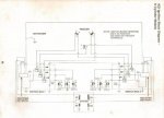
I don't know why but after having a power loss from my motor and suspecting an ignition problem as the culprit I came across the Mercury V6 ignition wiring diagram I became kind of obsessed with figuring out how the system worked .
Looking at the trigger winding arrangement with 120 degree displacement between windings I was really baffled on just how they were achieving trigger signals (gate pulse signals )to the switchbox SCR's at the required 60 degree interval to fire the spark plug coils . I read a post on another forum claiming the trigger wire connections between both switch boxes made a "Delta" winding configuration . After mulling that over for awhile I dismissed that being the answer due to the blocking diodes in the switchboxes . Next I contemplated the possibility of electronic timing networks being built into the switchboxes to sync all the firing pulses (that would work but be more complicated ).
The conclusion I came to was that the two trigger magnets must be mounted in the flywheel hub with a displacement of 60 degrees with the "North " pole leading the "South " pole by this amount . With a firing order of 1-4-5-2-3-6 as the flywheel rotates the "N" pole magnet crosses the #1 trigger winding producing a (Positive )voltage pulse to the switchbox firing cylider #1 .
60 degrees later the "S" pole magnet crosses the #1 trigger winding producing a (positive ) voltage pulse to the switch
box fiirng cylinder #4 . This would be repeated with the remaing two trigger windings firing all cylinders in order .
This would be the simplest way to make the system work . I did not want to know bad enough to remove my flywheel to verify the trigger magnet locations . Can anyone confirm if this is where the trigger magnets are situated in the hub?
PS : after investing all of this time in the ignition system I found the source of the problem was a bad fuel injector (open coil)


