New guy, help with Johnson Sea-Horse 18

blue_crush

Cadet
Joined
Mar 21, 2016
Messages
7
Hello, this is my first boat and I have never worked on an outboard so I'm still learning. I'm no stranger to car engines, so I have some mechanical ability.
I'm in the final stages putting my motor back together after rebuilding the carb and installing all new ignition systems (still couldn't figure out where the foam pads for oiling go..) and just wanted to double check something before I go any further.
After putting my flywheel back on, but not tightening it down. If I try to spin the flywheel by hand to check for spark, the entire base tries to move as well. This doesn't seem right. What am I missing here? I can provide a video if necessary.
Thanks for any help. All the post other people have provided have helped out a great deal and the vendors as well!!
 

racerone

Supreme Mariner
Joined
Dec 28, 2013
Messages
38,967
There is / should be a little bracket under one coil for the oiling pad.---The front coil I believe,------And you need to set the coils so that they do not drag on the flywheel.
 

Crosbyman

Vice Admiral
Joined
Nov 5, 2006
Messages
5,843
first you need diagrams to see where parts go ...need to know what year your engine is (model#)

the single felt pad locks in a 90 degree bent bracket which sits on an odd shaped post under a coil and rubs on the lobe cam. these clips are VERY expensive .Hope you find it

it needs no more than 2-3 drops of sae30 oil or so .

send me a PM with your e-mail so I can send you some links

you can visit the AOMCI site where oldies experts can also help out
 
Last edited:

blue_crush

Cadet
Joined
Mar 21, 2016
Messages
7
first you need diagrams to see where parts go ...need to know what year your engine is (model#)

the single felt pad locks in a 90 degree bent bracket which sits on an odd shaped post under a coil and rubs on the lobe cam. these clips are VERY expensive .Hope you find it

it needs no more than 2-3 drops of sae30 oil or so .

send me a PM with your e-mail so I can send you some links

you can visit the AOMCI site where oldies experts can also help out

It's an FD13, the new coils are actually just a tad shorter than the ones that were on it. I replaced one side at a time so I could use the other side as a guide. I even took pictures along the way as this is all new stuff to me. There wasn't a 90 degree bracket there when I took it apart.
So long story short, I should be able to slip the flywheel back on and freely turn it without the base moving, correct?
 

AlTn

Commander
Joined
Mar 9, 2010
Messages
2,813
correct, base < armature plate > shouldn't move with flywheel..the Sticky at the beginning of the Forum..Top Secret Files...scroll down to Universal Magneto Troubleshooting and it should clear up a few items for you
 

Crosbyman

Vice Admiral
Joined
Nov 5, 2006
Messages
5,843
blue crush... I got an empty PM from you I need your direct e-mail to send links because this site will auto-block certain HTTP for commercial reasons.

or got o a site called boatinfo.com to access the original maintenance manual from Waukegan Illinois johnson motors (twins of evinrude)

another site will give you all the parts layout, and part numbers but is is auto-blocked as explained above.

to adjust (basic) the timing just rotate the cam lobe to its high point whith the point's rubbing block openning the points to maximum opening. At the high point
of the cam lobe set the points at 0.20 repeat for the other points. The brown rubbing block should be just abot middle of the cam lobe marking "TOP"

you now must find a felt clip otherwise the rubbing blocks will wear down fastr requiring adjustments and replacements of the points
 
Last edited:

Crosbyman

Vice Admiral
Joined
Nov 5, 2006
Messages
5,843
racerone... thanks... fat fingers again ... almost quarter inch....that would have been really off

oldboat.....I did the link to BRP... seems to cover since 1968 only... this is a 59 engine..
 
Last edited:

Chinewalker

Fleet Admiral
Joined
Aug 19, 2001
Messages
8,902
The outside edge of the laminates MUST be flush with the machined surface just below the lams on the mag plate. If they extend outwards at all, they'll catch on the flywheel as you have noticed.

PM me if you still need the clip - I've got several...
 

oldboat1

Fleet Admiral
Joined
Apr 3, 2002
Messages
9,612
oldboat.....I did the link to BRP... seems to cover since 1968 only... this is a 59 engine..

good catch, Crosbyman. blue_crush -- keep it for future reference (or sister models, as the 18s stretched over quite a period).
 

racerone

Supreme Mariner
Joined
Dec 28, 2013
Messages
38,967
The Johnson model was marketed as a 20 hp in 1965 and earlier.versions were marketed as an 18 hp.
 

blue_crush

Cadet
Joined
Mar 21, 2016
Messages
7
Just noticed that the flywheel I received is from an FD14. Is it the same? I cant compare as I destroyed my old one trying to remove it..
 

cajuncook1

Chief Petty Officer
Joined
Sep 3, 2009
Messages
559
I posted this a while back to help a guy out, you might find some of the information useful.

​Cheers,
Cajun


- There is a process for evaluating the motor. If you are willing to take guidance we can help you out to determine what is going on with your motor.

* First thing is to check the compression yourself. Most auto places will loan out a compression tester for a deposit and money is refunding when you return it. Napa, Auto Zone, O'Reilys...etc.

Here is a video to show you how you can test your compression.


https://www.youtube.com/watch?v=PyCw4SiuT2I

Please report back your finds on compression.


**Second phase of diagnostics is to evaluate the ignition.


***Third phase of diagnostics is to evaluate the carburetor and the fuel delivery system.


By putting the spark plug against the engine block is not adequate assessment of the health of the ignition system. You need to get a spark checker and gap it to at least 1/4 inch. The spark should be able to consistently jump the gap and be strong blue snapping spark.

Here is a bunch of information that you can read and do the repairs yourself and know what is going on.

Here is some information that will help you evaluate your ignition system with the flywheel popped off.


Harmonic balance flywheel puller video

https://www.youtube.com/watch?v=Nz1st4XnsX4


Your going to need to inspect your point, condenser and coils. They are located under the flywheel. Hopefully all you need to do is clean and regap your points and you might be in business. Still check your coils and condensers and plug wires.


Here are two link to show you how to test your coils and condensers.

http://www.youtube.com/watch?v=KT8rk5QWgS0

http://www.youtube.com/watch?v=l6eSXYmENDY


How to replace your coils, points and condenser. Please take digital pictures as you go, so it will help you return everything back in the right order. Keep cheap zip lock bags available to put your parts in so you don't lose them. They are small.


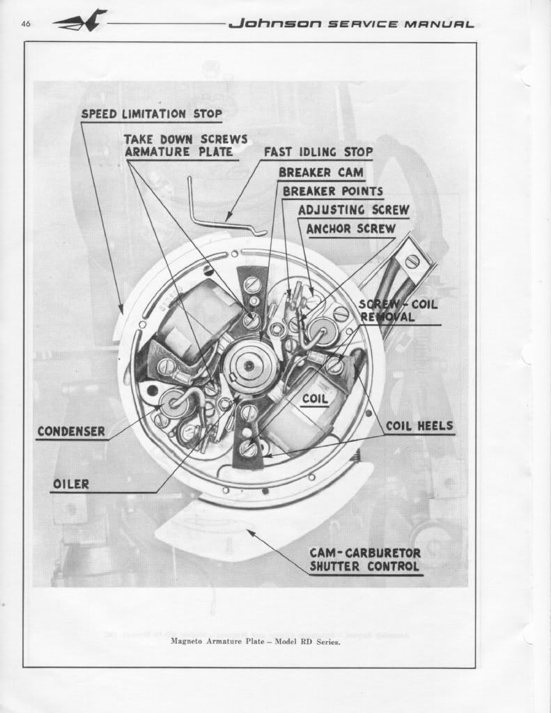
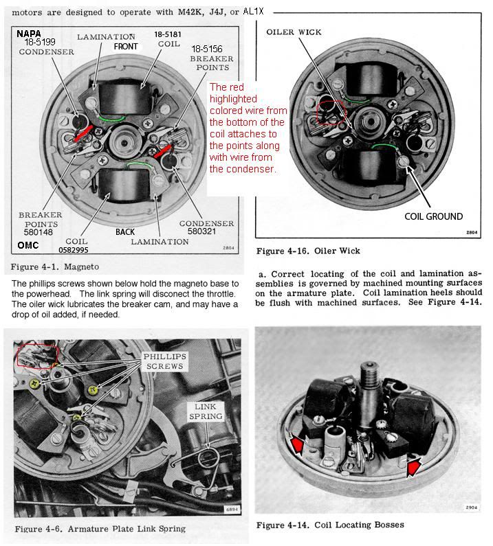
Here is a diagram of a generic OMC (Johnson/Evinrudle/Gale) ignition assembly. You will have to remove the coil designated for the top cylinder and put the oil wicker in. It should be already be coated with a very light oil. (not grease). The purpose of the oil wicker is to lightly lubricate the outside riding surface of the cam so the point shoes do not prematurely wear. If you look at the points they have little shoes that ride along the cam. Please make sure the (breaker)points cam is on the correct side or the ignition will be out of timing. It should have the word [highlight]top[/highlight] machine written on the side facing up.

Ignitionplateandoilwick.jpg


FYI: You can only set(gap) one set of points at a time. Put the flywheel nut back on(turn with a wrench or ratchet clockwise) to allow you turn the crankshaft. (Please remove both spark plugs to make it easier to turn the crankshaft and prevent accidental starting)

You gap the point to 0.020 when the point shoes is at the top(high point of the cam). It should have a mark along with the word top. Then you will turn clockwise to the next set of point 180 degrees and set those points the same way. You will notice that the point of the previous set will be closed and when you come around again they will open up. *** When they are open no current is allow through. This is how you set your timing with the points.***

When you go to set the point's gap. Very gently snug the anchor screw, then adjust the gap with adjusting screw and the feeler gauge until the feeler gauge is sliding through with slight resistance only. Then tighten the anchor screw. Repeat procedure with second set of points. Please make sure your hands are clean and the feeler gauge is clean, because oil on the points can foul them up and create resistance....poor or no no spark. ALways use a spark check to evaluate spark. It should jump minimum 1/4 inch. Blue sharp snappy spark.

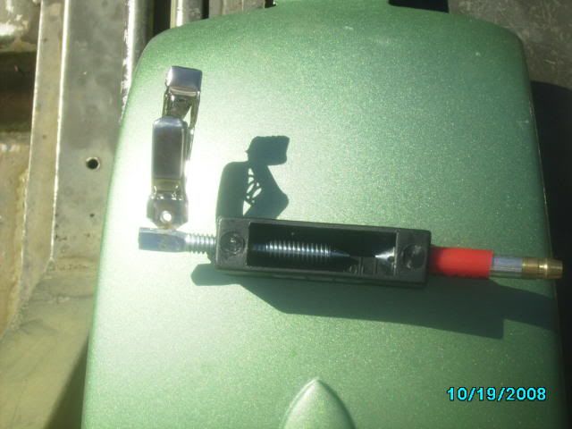
Here is a picture of a spark check...Cheap $6

sparktesterpic.jpg


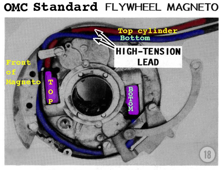
Here is a picture of how to tell which wire is going to the correct cylinder. Thanks to Garry for providing the picture on other post.


TopCyl.jpg


If your using the existing wires then cut about 1/4 inch of end going the coil, so you have clean un-oxidized copper contacting the spiking in the coil. Twist the end of the spark plug wire onto the coil spike. If you have replaced the wires, make sure they are 7mm copper metal core and not the automobile stuff.

***** Please make sure two things*****

1.) Make sure all the wires are tucked away under the flywheel and not rubbing up against the cam or crank, because with will eventually get damage and create a short, then no spark!!

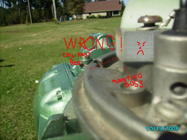
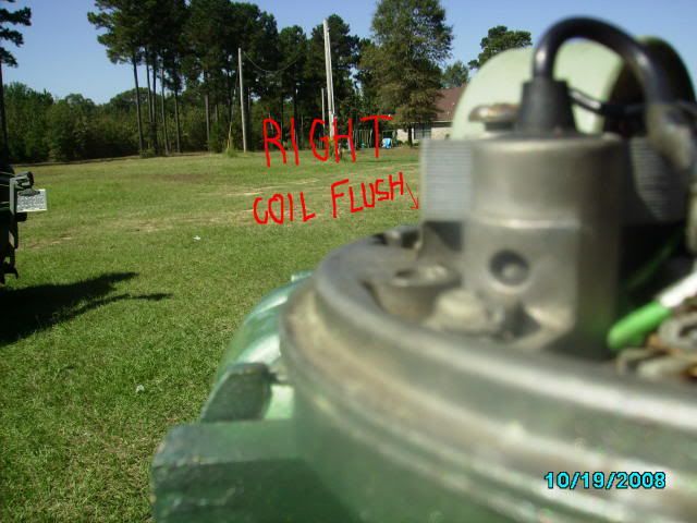
2.) Make sure the coil heels (ends) are evenly lined up with the mounting boss.

Here are some pictures. (Compliments of JBJennings..nice fella)

wrongcoilmount.jpg


rightwaytomountcoil.jpg


Lining up the coil heel with the mounting boss prevent damage of the coils and the flywheel magnet, prevent rubbing as the flywheel turns.

[highlight]*** Make sure the throttle is advanced to that start position***[/highlight]


Here is another picture that Garry (thanks Garry!!) supplied on another post with some modification.

OMC_Stdwithwirecolors.jpg


Both diagrams, should answer your questions.
 

oldboat1

Fleet Admiral
Joined
Apr 3, 2002
Messages
9,612
Cajun -- thanks. Like your work. youtubes some of the best out there!
 
Top