Parts I.D. and info

Stevebandl

Cadet
Joined
Nov 8, 2012
Messages
26
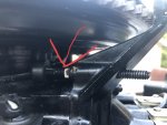
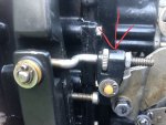
Hello I'm fairly new to the forum and also to outboard mechanics but I'm trying to learn. I have an 85 Ranger 370V with an 89 Evinrude 150XP E150STLCEM. I feel that if you're going own a 30 year old motor and trust it on the lake, you better know something about it. So I try to avoid taking my motor to a mechanic and I've learned a lot as a result. I just replaced the stator and timer and now I've for out that my voltage regulator is bad so I'll be pulling the flywheel off again to do that the first of next week. There's still a lot I don't know so I will be posting some pics and would appreciate it if some of you pros. would identify the part I post and maybe give a little detail about their function.
Trying to post some pics now but there's some issue with the server. To be continued
Thanks in advance for your help!..
 

Attachments

  • photo317485.jpg
    photo317485.jpg
    541.7 KB · Views: 0
  • photo317486.jpg
    photo317486.jpg
    608.6 KB · Views: 0

flyingscott

Fleet Admiral
Joined
Apr 8, 2014
Messages
8,229
First pic is the max timing screw Leave it alone. There are VERY few reasons to touch that so leave it alone. Second pic that adjuster is used in the link and sync and will seldom need to be touched.
 

Stevebandl

Cadet
Joined
Nov 8, 2012
Messages
26
Thanks! Since I changed the stator and timer I'm trying to make sure the timing is right and I know very little about how to set timing. I have a pic but the file size is too big to upload. I did the test to verify that # piston was at the top to check TDC. There is a painted white line on the flywheel on the top dead center mark. The pointer on the motor is pointing almost dead on the painted mark. I believe my timing is supposed to be set at 7 degrees + or - 1 degree. So, when the motor is running I'm thinking that the white painted line should be flashing approx. 7 degrees before the pointer? And the pointer probably has approx. 1/4 inch of adjustment in it to move from side to side. How do you know where to lock it down?
 

jakedaawg

Rear Admiral
Joined
Jun 26, 2012
Messages
4,275
Place motor at TDC of cylinder 1. Adjust pointer so it lines up with TDC or "0" of the scale in the flywheel. To determine which side of scale is BTDC remember that flywheel turns clockwise.
 

jakedaawg

Rear Admiral
Joined
Jun 26, 2012
Messages
4,275
As for oversize pics...there are several pic resizing apps available free. I am not the guy to say how or which to get though, that's what 14 year old nephews are for;)
 

Stevebandl

Cadet
Joined
Nov 8, 2012
Messages
26
Thanks! I'll look into that.:) Knowing that my voltage regulator is bad, will that it anyway affect the timing? I probably won't run it again before I get that fixed but I was just curious.
 

racerone

Supreme Mariner
Joined
Dec 28, 2013
Messages
38,892
Caution DO NOT adjust timing until you fully understand the adjustments.-------Fact-----Only set maximum timing advance.----The timing where the motor idles looks after itself !-----Idle timing may refer to the point where throttle plates open.-----Read manual 3 times before you try and make adjustments !
 

oldboat1

Fleet Admiral
Joined
Apr 3, 2002
Messages
9,612
Think I would definitely replace the regulator first, if you know it's bad. Water cooled regulators can be a fire hazard -- want to be sure the water pump is working right, and that the powerhead is getting a full supply of cooling water. Running on muffs may not be a good idea. How did you determine the regulator was bad, btw? You may be having operating problems caused by a faulty regulator, rather than timing adjustment.
 

Stevebandl

Cadet
Joined
Nov 8, 2012
Messages
26
One of the guys that’s been helping me on the BBC forum told me to check the voltage on the battery with engine off then running. Off it was 12.8v. Running 12.7v. So from that he told me the regulator was bad.
 
Top