Possible to connect 8 pin to 6 pin connection?

clueless75

Petty Officer 2nd Class
Joined
Jan 30, 2015
Messages
102
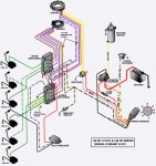
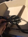
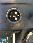
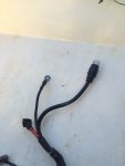
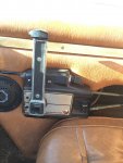
I have a 1975 Merc 850 with the 6 pin connection on a boat that originally came with a 1981 90hp motor that ws siezed with the 8 pin connection, and im planning to fit the two somehow. I'm wondering if someone has ever done this or if anyone has any advice? The 1981 90hp six cylinder has the 6 coils whereas the 850 has the distributor and switch box. The controls are for the original 90hp, but doesn't fit the 850 (of course). I do have the controls for the 850, but installing them would be a real pain due to the layout of the boat, so I'd rather just jimmy something up temporarily before summer ends. My plan is to fix the 90hp and install it over winter, so it'd be silly to install the 850 controls, use it a few times, then uninstall them and put the 90hp controls back in. I wasn't able to find any wiring diagrams of the control box but I have attached pics. I do have the wiring diagram for the 90hp though if it helps. The current controls have the 8 pins plus the positive for the starter solenoid as well as a negative which came from the starter ground. Any help would be greatly appreciated! Thanks
 

Attachments

  • photo250652.JPG
    photo250652.JPG
    114 KB · Views: 8
  • photo250653.JPG
    photo250653.JPG
    89.6 KB · Views: 8
  • photo250654.JPG
    photo250654.JPG
    54.5 KB · Views: 7
  • photo250655.JPG
    photo250655.JPG
    108.8 KB · Views: 7
  • photo250656.JPG
    photo250656.JPG
    179 KB · Views: 8

GA_Boater

Honorary Moderator Emeritus
Joined
May 24, 2011
Messages
49,038
You need adapter.......CDI-421-4401

+1. This adapter connects earlier side mounted connector boat harnesses to the newer internal style. Plug and play.

Out of stock in the iboats store, Google Fazt's CDI number.
 

clueless75

Petty Officer 2nd Class
Joined
Jan 30, 2015
Messages
102
Thanks for the lead, but I don't have $200 to spend on a plug that I probably wouldn't use much. I can't find anything available for cheaper, plus I live in Canada so shipping and what not would add a lot of extra $$. I'd much rather do it the cheaper way - myself! Just a temporary solution is all I'm looking for :)
 

Chris1956

Supreme Mariner
Joined
Mar 25, 2004
Messages
28,122
The ignitions are compatable, as evidenced by the plug adaptor. You will need to find some male and female connectors (bullet plugs??) and make a wiring harness. Alternatively, You could use part of the motor harness from the 900, and just replace the 850 wiring harness with that, with a few simple mods.

Your 850 will need battery +, Ground, Ign power (+12VDC), choke, tachometer, and starter solenoid. The 900 harness should have all of those, but you may need to extend some of the wires. The wiring harness colors of the 900 harness may be different, as it changed in the early 80s'
 

clueless75

Petty Officer 2nd Class
Joined
Jan 30, 2015
Messages
102
Thanks Chris, the colours did change a bit. I attached a pic of the internal wiring harness diagram (in the first post) of the 900, which has different colours as the 850, as well as a few extra wires such as the black and yellow one that goes to the switch boxes. Otherwise, I would probably be able to figure it out myself. I'll just use the 900's wiring harness and use that diagram to help me, hopefully I don't screw anything up. I'll get around to it sometime in the next few days!
 

Chris1956

Supreme Mariner
Joined
Mar 25, 2004
Messages
28,122
OK, some possible help. The 900 wiring colors should be as follows: Red is |12vDC to the red terminal on the switchbox. Black is ground and connect it to the frame. Yellow/black to the choke solenoid. Black/yellow is unused. Yellow/red to the starter solenoid. Grey to the rectifier for tach signal. Purple to the white connector (next to the red connector) on the switchbox.
 

clueless75

Petty Officer 2nd Class
Joined
Jan 30, 2015
Messages
102
Okay so there is no purple wires, there is a yellow/black that went to the choke, two small blacks with one on the solenoid and one on ground, a small red that went on the big post underneath the big 12V wire on the solenoid, a yellow/red wire that went to the solenoid, three black/yellow wires with two that went to each switchbox, and one went in the Mercury switch, then the red and gray for the rectifier. The main plug from the controls has both the positive (for the solenoid) and negative (which came from the bottom of the starter bracket). Now the 850 has the switchbox with the top being green going to the coil, the brown which has a brown wire coming from the harness (tach I assume, although it isn't on the rectifier), red which comes from the plug and rectifier, and white which comes from the harness. Now what do I do with the white and red posts on the switchbox? Should I put the red that was under the main post on the solenoid (on the 900) on the red post on the switchbox? And I have no clue about the white and what to put there.
 

clueless75

Petty Officer 2nd Class
Joined
Jan 30, 2015
Messages
102
No Title

The wiring on the 900 is the exact same as the pic that I have attached, with the exception of one extra ground wire, no fuse, and no idle stabilizer.
 

Attachments

  • photo250653.JPG
    photo250653.JPG
    89.6 KB · Views: 11

clueless75

Petty Officer 2nd Class
Joined
Jan 30, 2015
Messages
102
Does anyone know why there isn't a white or purple 12V wire to go to the switchbox? Would I be able to run the motor without it? Would I be able to perhaps make one? Or would I be able to use the black/yellow wire(s)? Any help would be greatly appreciated!
 

Chris1956

Supreme Mariner
Joined
Mar 25, 2004
Messages
28,122
OK, the 900 doesn't need ign power to run, as it is alternator driven ignition. That is likely why they didn't pull it through. Sounds like you would need to pull a power wire to make it work. The easiest way is to pull a wire from the fuel gauge or tach, to the motor to power the ign.

​Alternatively, if you are not using the tachometer signal wire(grey), you could use that to drive the ignition. A lot of those MerControls have the three prong connector on the front. You could move the grey wire from the rectifier to the switchbox white terminal and jumper from the power prong in the connector to the tach prong in the connector.
 

Chris1956

Supreme Mariner
Joined
Mar 25, 2004
Messages
28,122
Using the black/yellow wire would require you to open the MerControl and resolder the black/yellow to replace the purple wire.
 

clueless75

Petty Officer 2nd Class
Joined
Jan 30, 2015
Messages
102
Alrighty thanks for the help. I assumed I would need to make an ignition switch, so I guess I'll just wire one up to the front as a separate switch (maybe hide it a bit and a thief wouldn't know how to start it heheh). I'll get around to it today. The controls aren't a MerControl, they're the quicksilver one and it doesn't have the three prong connection, but instead like 5 or so circles that plug in. I'd much rather just leave it as simple as possible so I wouldn't need to do much to get the old motor back on and as easy as possible! Resoldering wires from the control would just be a mess for me... Anyways, thanks for the help Chris!
 
Last edited:

clueless75

Petty Officer 2nd Class
Joined
Jan 30, 2015
Messages
102
Okay, so I hooked everything up and attached the 12V wire from white on switchbox to the tach positive. Nothing happens. Not even choke. I have 12.75V on the battery, 12.74V on the positive post on the solenoid, but nothing else. Connections are all clean, battery is charged and good, wiring looks good, but I get nothing. No voltage to the positive on the tach when the key is in any of the three positions. Same thing in the motor - no voltage on any key setting other than the positive on the solenoid. Did I screw up anywhere? All fuses inside the boat are good, and so is most of the wiring. Previous owner said everything worked as it should back when he last used it a few years ago, so everything should work now... There are only three wires to the battery other than the two main positive and negative for the motor. One is a fused positive, around 16 gauge and then is connected into more of a 14 gauge a few inches down past the fuse. Weird, but it worked for the previous owner. The other are two negatives (or so I think). But those are just for powering the accessories, right? As for the tach harness, there are five wires but two of them aren't used (I forgot what colour) and the other three are connected to the tach. I tested for voltage on all of the wires, none of which showed any voltage. The plug into the controls are clean and looking good. I'm very confused
 

Chris1956

Supreme Mariner
Joined
Mar 25, 2004
Messages
28,122
Clue, I am not sure what state the ignition is in now. Did you remove the original wiring harness from the 850 and replace it with the wiring harness from the 900?
 

clueless75

Petty Officer 2nd Class
Joined
Jan 30, 2015
Messages
102
Yup. Wired everything where it is supposed to go, the only difference is that on the 900 the small red wire was attached underneath the big red wire on the big post of the solenoid, whereas on the 850 I put that wire to the red on switchbox. As well as the three black/yellow wires that aren't connected to anything. It's weird because even if I hooked some things up wrong, I know the choke is hooked up properly so shouldn't that at least work??
 

clueless75

Petty Officer 2nd Class
Joined
Jan 30, 2015
Messages
102
I left the battery and all its poles attached last night, when the battery showed 12.75V, now it's at 12.4V, so something must've been taking up juice? And the motor shouldn't take so much juice right?
 

clueless75

Petty Officer 2nd Class
Joined
Jan 30, 2015
Messages
102
I took apart the controls and all wiring looks okay, although one wire (I'm not sure what it's attached to?) is yellow/red and seems to not be connected very well. It isn't connected to the key plug ins or to the tach harness plug, nor to the kill switch. Maybe neutral lock switch? Anyways, it doesn't show any voltage with the key in any position. Also, when I've been testing for voltage in some places, my digital multimeter shows a little negative sign in front of 0.00 (so it shows -0.00 sometimes) when tapped on certain surfaces. Does anyone know what it means? This is all very confusing as all wires look good and battery is good and connections are good and everything is hooked up as it should, yet no voltage anywhere except on the positive terminal on the starter solenoid, and the battery of course. I've never really had anything like this, and I'm clueless!
 

gm280

Supreme Mariner
Joined
Jun 26, 2011
Messages
14,605
I took apart the controls and all wiring looks okay, although one wire (I'm not sure what it's attached to?) is yellow/red and seems to not be connected very well. It isn't connected to the key plug ins or to the tach harness plug, nor to the kill switch. Maybe neutral lock switch? Anyways, it doesn't show any voltage with the key in any position. Also, when I've been testing for voltage in some places, my digital multimeter shows a little negative sign in front of 0.00 (so it shows -0.00 sometimes) when tapped on certain surfaces. Does anyone know what it means? This is all very confusing as all wires look good and battery is good and connections are good and everything is hooked up as it should, yet no voltage anywhere except on the positive terminal on the starter solenoid, and the battery of course. I've never really had anything like this, and I'm clueless!

Not sure about everything else because I haven't read this entire thread, But I can tell you that your meter reading -0.00 means your meter is at zero and reads neither a positive or negative voltage. Some times auto zeroing digital meter read -0.00 or even 0.00 and even flips back and fourth. So no worry about such a reading.
 
Top