Proline 2510 Walkaround - Wiring and water system info

TBarCYa

Senior Chief Petty Officer
Joined
Apr 13, 2005
Messages
781
I'm rebuilding a Proline 2510 Walkaround and am in need of some information. I found the owners manual online but it is very poor quality and doesn't show the locations of the holding tanks or how the drains run. If anyone has any info on this boat it would be immensely helpful.

Specifically, I'm looking for a much clearer wiring diagram than what is in the PDF of the owner's manual. Also, there are two storage tanks on the starboard side behind the throttle and behind the head that I need to identify. I'm sure one is the fresh water tank but this boat doesn't have a flush head so I'm wondering if they installed the black water tank but just not the flush head / macerator? I'm kinda hoping this is the case. Lastly, the floor drain in the head appears to be clogged and I need to know if that just runs into the bilge or if it is supposed to run directly to a thru-hull.

Any and all information on this boat would be much appreciated. We're at the beginning of a long project and right now the lack of available information is the biggest hurdle.

Thanks.
 

Scott Danforth

Grumpy Vintage Moderator still playing with boats
Staff member
Joined
Jul 23, 2011
Messages
50,426
your best bet is to call customer service (not email, however call) at proline. https://prolineboats.com/

regarding the plumbing, it may be different with every boat, even if the boats are the same. unlike automobiles where there are drawings showing each and every nut and bold, boats are build on napkin sketches on the shop floor.

however regarding the wiring. wiring color codes are standard [h=2]American Boat and Yacht Council Standards[/h]
BlackGroundNegative / Neutral Main Return
Blue-StripeTilt up and or trim outTilt and or trim circuits
BrownAlternator Charge LightGenerator Terminal or Alternator Auxiliary Terminal to Regulator
Generator ArmatureGenerator Armature to Regulator
PumpsCircuit Breaker or Switch to Pumps
Brown w/YellowBilge BlowersCircuit Breaker or Switch to Blower
Dark BlueCabin & InstrumentCircuit Breaker or Switch to Lights
Green or Green w/Yellow StripeBonding SystemGrounding Wires (if insulated)
Green StripeTilt down and/or trim inTilt and or trim circuits
GreyNavigation LightsCircuit Breaker or Switch to Lights
TachometerTachometer Sender to Gauge
Lt. BlueOil PressureOil Pressure Sender to Gauge
OrangeAccessory FeedAmmeter to Alternator or Generator
Common FeedDistribution Panel to Accessory Switch
FeedAccessory Circuit Breakers or Switches
PinkFuel GaugeFuel Gauge Sender to Gauge
PurpleIgnitionIgnition Switch to Coil & Electrical Instrument
Instrument FeedDistribution Panel Electrical Instruments
RedInstrument FeedDistribution Panel to Electrical Instruments
Power FeedsPositive Main Power (particularly un-fused)
TanWater temperatureWater temperature sender to gauge
YellowGenerator FieldGenerator to Regulator Field Terminal
GroundNegative / Neutral Main Return
Yellow w/RedStarting CircuitStarting Switch to Solenoid

COLOR ITEM USE
 

TBarCYa

Senior Chief Petty Officer
Joined
Apr 13, 2005
Messages
781
Scott, I was telling my wife last night that by the time we're done with this boat I'm going to have that ABYC chart memorized. Unfortunately, since most of the wiring is burned I can't trace colors from one place to the next and I never knew the boat before the fire so I don't know what / where everything is. As an example, there's a switch and a spigot at the starboard quarter that I assume turns on a raw water pump for the spigot. It would make sense that it's fed from the distribution block behind the battery but I assume there's a chance it comes from the helm since there's a switch up there for a water pump.

Thanks!
 

alldodge

Moderator
Staff member
Joined
Mar 8, 2009
Messages
42,699
Looking at the Proline website I find the standard equipment comes with fish boxes forward with overboard drains, and fish boxes with macerator's. So no head, the unit uses it to chop up anything before going over the side.

A good wiring plan as negative and positive buss bars at the helm and stern would be best method. I would bet Proline did the same.

Run heavier cable to each bar from the bats, at least 10 if not 8 gauge, with fuses. A fuse panel can be used where a buss bar might be located, or in conjunction with.

From there just start running wiring to needed circuits
 

TBarCYa

Senior Chief Petty Officer
Joined
Apr 13, 2005
Messages
781
That is pretty much how it's setup now... Bus bars at the helm and at the battery with a circuit breaker at the battery. Those appear to be in good shape, it's just the wiring in between that's the issue.
 

alldodge

Moderator
Staff member
Joined
Mar 8, 2009
Messages
42,699
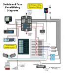
This gives the general wire up, but there all pretty much the same, unless something needs to be controlled at two locations

Gen Wiring Diagram.jpg
 

TBarCYa

Senior Chief Petty Officer
Joined
Apr 13, 2005
Messages
781
I started this thread in April and here we are in October and the wiring is FINALLY done. Well... Almost. There's one pump on the transom that I haven't wired because I can't figure out what it does. It appears to feed the bait boxes but is T'd to a thru hull.. There's also some stuff that I want to add like additional cockpit lights but that's going to wait until she's in the water and we decide if we're keeping her.

Ultimately I ended up installing about 400' of wire covering both DC and AC systems, 3 additional bus bars, an additional 6 position fuse box and new engine harness to the helm. I also replaced the steering, throttle and shift cables and I have about 8 6" deck plates to replace. She's back together and once I can get the bad fuel pumped out of the tank she'll get some good gas and bottom paint and be ready for the water.

Thanks for the help with the wiring questions. I'm pretty much an expert at wiring this boat by now.
 
Top