Schematic Diagram for Vintage Faria Tachometer

svonadym

Recruit
Joined
Aug 14, 2025
Messages
5
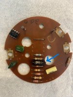
Hi all! I suppose this is a long shot, but my new-to-me 1993 Bayliner Classic (1952CN) came with a Faria Tachometer that doesn't work. It has proper 12+V, ground and signal from the engine, so I opened it up to see if I could repair it. The first resistor on the 12V input side is burnt to a crisp. I'd like to try to solder in a replacement cuz I'm cheap frugal, but can no longer read the colors to determine the size. Anyone know what size resistor it might take or where to find a schematic of the internals of an early 90's Faria tachometer? I couldn't find anything online. I'll reach out to Faria too to see if they'll help.
 

StewartL

Cadet
Joined
Jul 23, 2025
Messages
27
Try contacting Faria directly they might have old schematics. If not, check boating forums or eBay for a used tach to salvage parts. A burnt resistor often points to a bigger issue, so a replacement gauge might be the safer bet.
 

mike_i

Lieutenant Junior Grade
Joined
Jun 28, 2017
Messages
1,004
I agree with both above. It's unlikely the manufacturer will help you dig in to the gauge to fix it and there's a reason the resistor burnt. Save your time and hassle trying to fix it and just replace it.
 

svonadym

Recruit
Joined
Aug 14, 2025
Messages
5
Thank you all for your responses. I contacted Faria, but as suspected they tell me they don't have that information (old unit). They didn't give an indication either way if they would for a newer unit. I've already ordered a replacement, but I always prefer to try to fix things. Thanks again.
 

kd4pbs

Petty Officer 2nd Class
Joined
Mar 5, 2012
Messages
142
Are you sure that's a resistor? Alone and in series with the supply would be an odd place for a resistor. I'd love to see a picture of both sides of the circuit board to offer an educated guess as to what it is.
 

svonadym

Recruit
Joined
Aug 14, 2025
Messages
5
Thank you for your offer. See below. It sure looks like a resistor to me, but appreciate your input.
 

Attachments

  • IMG_7839.jpg
    IMG_7839.jpg
    2.5 MB · Views: 10

kd4pbs

Petty Officer 2nd Class
Joined
Mar 5, 2012
Messages
142
Yeah, that’s a resistor for sure. The smaller ones are 1/4 watt ones and the one that is burnt is a half watt resistor. It makes sense that it would be a higher power resistor if it is on the main power feed. I would guess that it would be somewhere under 100 ohms. The thing is, something else in there shorted to cause that one to burn up. Do you have a way to take a picture of the other side and annotate the connections for the power and the tach signal? I know it’s rather a moot point right now since you have another one coming, but I like challenges like this with a moderately simple circuit and no schematic diagram.
 

kd4pbs

Petty Officer 2nd Class
Joined
Mar 5, 2012
Messages
142
The chip in the upper left-hand side is a CS 2917 which is a frequency to voltage converter. That’s what takes the tachometer signal and outputs a voltage to drive the meter. It looks like this was made sometime around 1983 according to the date code on that chip. Quite probably that diode underneath that resistor failed short or somebody had connected the battery backwards at some point in time.
 

mike_i

Lieutenant Junior Grade
Joined
Jun 28, 2017
Messages
1,004
What looks like a diode next to it may be fried too? The only way to confirm is to remove it and check with an ohm meter. If you're going to mess with the resistor remove it, maybe the under side of it isn't too burnt to read the color bands.
 
Top