Tach Issue

Nheels

Petty Officer 2nd Class
Joined
Mar 8, 2021
Messages
135
Hello, all. Engine is 2008 Volvo Penta 5.7gi-300-J with Faria guage.

Anyone know if tach recieves signal from ECM or is it from ignition coil? From what I've read signal originates from negative post on ignition coil, but does it then get picked up by ECM and transmitted to tach?

If there is advice on how to test the signal, it would be appreciated! I believe my coil has a plug connector.

Thanks!
 

Nheels

Petty Officer 2nd Class
Joined
Mar 8, 2021
Messages
135
grey wire off of the coil
Morning. In most setups, would that Grey run right to the tach then?

I believe it is a part of a wiring harness that plugs into the ignition coil.

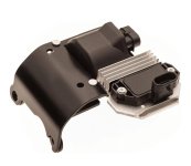
For example, if this picture is the coil, where is the grey wire connect to for me to test it specifically?1000003527.jpg
 

Scott Danforth

Grumpy Vintage Moderator still playing with boats
Staff member
Joined
Jul 23, 2011
Messages
51,306
50-and-57-gi-gsi-jpg.355612


image borrowed from this thread. https://forums.iboats.com/threads/wiring-harness-for-5-7gif.753494/
 

kd4pbs

Petty Officer 1st Class
Joined
Mar 5, 2012
Messages
219
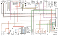
This one is more specific to the MPI engine. Gray wire goes from coil to the 10-pin connector. From there, it goes wherever your manufacturer wanted to route it to your tach.
Faria's air core movements are prone to failure. That's what the issue was with the Faria tach on my 5.7Gi. That one took some surgery to repair. Repaired because it wasn't cheap to replace. It's one of those forsaken three-in-one multifunction gauges that are way overpriced.
 

Attachments

  • 5.0 5.7 GI GXI Wiring Diagram.png
    5.0 5.7 GI GXI Wiring Diagram.png
    2.2 MB · Views: 5

Nheels

Petty Officer 2nd Class
Joined
Mar 8, 2021
Messages
135
This one is more specific to the MPI engine. Gray wire goes from coil to the 10-pin connector. From there, it goes wherever your manufacturer wanted to route it to your tach.
Faria's air core movements are prone to failure. That's what the issue was with the Faria tach on my 5.7Gi. That one took some surgery to repair. Repaired because it wasn't cheap to replace. It's one of those forsaken three-in-one multifunction gauges that are way overpriced.
That's a great diagram. Thanks. It appears like I'm going to have some difficulty running a continuity test on the signal wire in this case.
My tach is just the standard with digital hour meter. I just got a replacement, but hoping it still is a lose wire or something. It's interesting because it is getting power, but reads a steady 200rpm.
 

kd4pbs

Petty Officer 1st Class
Joined
Mar 5, 2012
Messages
219
Mine showed a steady 1000 RPM because that’s where the movement had a catch in the mechanism. The quadrature voltages feeding the air core movement were correct, but the rotor was dragging at many different spots along its range and it decided to get stuck at 1000. With the cost of a single gauge with hour meter I would just replace it. I would also go a step further and put it on a 12 V supply with a signal generator to activate the hour meter so that it reads the same as what I was replacing, but not everybody has a signal generator laying around. You can use a multimeter to check the signal going into the tach. If your multimeter has a frequency setting, it will show something more than zero when running and if it only has voltage reading, put it on AC and it will read something greater than when not running by a handful of volts.
 

kd4pbs

Petty Officer 1st Class
Joined
Mar 5, 2012
Messages
219
Oh, and the diagram has one error in it. It is an Easter egg put in to identify it by the maker 😏
 
Top