Rivergator
Petty Officer 1st Class
- Joined
- May 7, 2013
- Messages
- 226
I am in the process of putting my whole Alpha One gimbal housing assembly back together. Every component of it has been gone over, repaired, serviced, painted. Anything that was not up to par has been replaced. The gimbal ring is back in the gimbal housing, both bellows have been properly installed on the gimbal housing end, the clamps are in the right position, the water hose is securely attached to the 3/4" nylon water tube and the bell housing water hose brass connector and the bell housing is loosely installed on the ring with the hinge pins. I know some of you prefer to install the bellows on the bell housing first and then push it on to the gimbal housing, but in my estimation it will make it rather difficult to reach the clamps or adjust them so you can reach them and since I already did it the other way I decided to leave well enough alone. However within a very few, very frustrating minutes I discovered and concluded that slipping the U-joint bellow over the bell housing sleeve was nothing short of a monumental b*tch. At this point I was wondering how the factory originally did install these buggers in less then 3 hours per unit without special "wunder" tools or go crazy and quit their job. So I did some thinking and came up with the following tool and in less than an hour the U-joint bellow was in place, easy, nice, snug and proper. I could have done it in less time but I needed to get the feel for it knowing when the bellow was properly seated and the rubber lip was securely seated in the groove of the bell housing sleeve. The first 2 times after I thought I got it, when I pulled up the bell housing the bellow slipped off, so I tried it again and pulled up the bellow some more and by the 3rd try it was done.
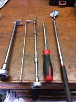
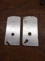
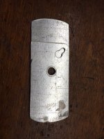
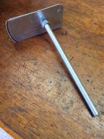
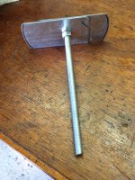
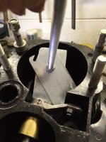
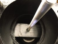
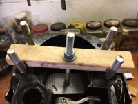
Pic #1 Tools needed or come in handy. From left to right: Tool to tighten center nut, tool to pull up exhaust bellow, tools needed to tighten clamps, mirror to see what needs to be seen. Pic #2 Fabricate a strong, precise plate assembly (I used an 4" electrical box cover from Home Depot $1.59), cut it in half and made a strong plate that when extended (see pic #3) fits exactly into the harmonica folds of the bellow. Pic #4 shows 3/8" threaded 9" rod, nuts, washers and shows tool in folded position. Pic #5 shows tool in extended position. Pic #6 Line up and start bellow on sleeve, make sure clamp is lined up for easy access to tighten it later, now insert folded tool in to bellow and position it and then turn the 2 halves until they are fully extended and then use first tool shown in Pic #1 to tighten the center nut on rod (see pic #7). Pic #8 use a properly drilled and cut to size piece of wood, install it on top of the bell housing and now you can easily pull up the bellow by turning the nut on top of the wood until the bellow is exactly where you want it, properly seated on the sleeve, you have both hands free for checking things and dealing with the clamp without that bellow moving or loosing its position. Now use tools 3 and/or 4 to tighten the clamp reaching up from underneath --- Done! Happy boater.
I then proceeded to do the exhaust bellow using the second tool in pic #1 pulling it up on the sleeve, no problem there. In order to make that job A LOT easier I temporarily removed the upper shift shaft lever assembly. When you do that, pay attention to the nylon washer under the lever when you re-install it and apply locktite to the screw. --- Job done --- Abita Time!