Jeremy1980
Cadet
- Joined
- Jun 6, 2015
- Messages
- 14
I recently purchased a boat with what is presumed to have a 92 johnson 120hp V4 outboard. I am trying to install a tilt/trim gauge. The boat currently has tilt/trim with foot controls and the side button on the outboard. Both work with no issues. The issues i need help with are below:
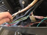
1. There is a limit switch currently mounted, but there is nothing on the bar that will press the rubber pin in. What goes there? Also the wires leading into the cowl from the limit switch has 2xgreen w/white stripe wires that aren't plugged into anything. Where do they plug in?
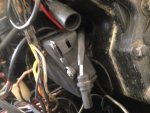
2. The previous owner removed the sender assembly off of the transom bracket but left the wiring. The wiring harness is ran into the cowl and tied in to what i believe is wrong? should there be some type of plug on the end of this that possibly plugs into something near the junction box?
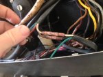
3. The 5x wire harness (red,green,blue, white black) has the white and black clipped after entering the cowl. Those wires that would be coming from the sender seems like they are tied into the wires where these were cut? Please help me to find that out.
4. Right above the tilt/trim junction box there is a 4 pin plug tied into the boats main wiring harness. Is this suppose to be plugged into something?
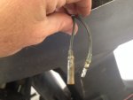
5. Coming out of the junction box is a 2 pin (female) plug. is this what the sender/ limit switch suppose to be plugged in?
6. Lastly the tilt/trim (5 wire) wiring harness that runs to the foot control, the white/black wire is not hooked up to anything. Would this be hooked up to the gauge somehow or what wires would i run to the gauge.
So as you can see im in a bind. Please help me figure this birds nest of wires out. Can upload more pictures if needed..Thanks
1. There is a limit switch currently mounted, but there is nothing on the bar that will press the rubber pin in. What goes there? Also the wires leading into the cowl from the limit switch has 2xgreen w/white stripe wires that aren't plugged into anything. Where do they plug in?
2. The previous owner removed the sender assembly off of the transom bracket but left the wiring. The wiring harness is ran into the cowl and tied in to what i believe is wrong? should there be some type of plug on the end of this that possibly plugs into something near the junction box?
3. The 5x wire harness (red,green,blue, white black) has the white and black clipped after entering the cowl. Those wires that would be coming from the sender seems like they are tied into the wires where these were cut? Please help me to find that out.
4. Right above the tilt/trim junction box there is a 4 pin plug tied into the boats main wiring harness. Is this suppose to be plugged into something?
5. Coming out of the junction box is a 2 pin (female) plug. is this what the sender/ limit switch suppose to be plugged in?
6. Lastly the tilt/trim (5 wire) wiring harness that runs to the foot control, the white/black wire is not hooked up to anything. Would this be hooked up to the gauge somehow or what wires would i run to the gauge.
So as you can see im in a bind. Please help me figure this birds nest of wires out. Can upload more pictures if needed..Thanks