Tilt trim relay wiring - Need Help!

caisson1

Cadet
Joined
Oct 23, 2005
Messages
15
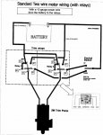
Hi, I have found several different posts with how to wire my relays, but they are conflicting. One shematic showed only 4 posts on the relays which I think is a Single pole single throw. It didnt' work. Another said to use a 5 post (STDP) and my battery cable sparks when I try to put it on so something isn't right.

I have a 17' Charger w/ '77 Chrysler 120HP and a two wire tilt motor. (Green and Blue wires) Works fine when I put them on the battery. Reverse the wires and it goes in opposite direction just fine.

Need help with wiring to relays and 3 position switch. My five posts on my relays are labled 30, 85, 86, 87, 87. Can anyone help me?
Thanks,
Chris
 

Frank Acampora

Supreme Mariner
Joined
Jan 19, 2007
Messages
12,004
Re: Tilt trim relay wiring - Need Help!

It becomes simple if you just realize that both these relays are default to ground when not activated.

Now, most of them have a schematic molded right into the case and the numbers molded into the bottom at each terminal.

We'll start at the switch: you need a MOM momentary on, off, momentary on. Run a hot 12 volt feed to the switch. The switch is only signal voltage--very little amps so you don't really need to fuze it. The 12 volt feed goes to the center pole of the switch. Use blue and green wires from the switch to the relay. Blue goes on the bottom terminal of the switch because it is the up signal and green goes on the top terminal.It doesn't matter if you use 85 or 86 terminal but be consistant. Run blue wire to 85 on one relay and green wire on the 85 terminal of the other relay. Run a common ground from both 86 terminals of both relays. This circuit activates either one of the relays depending on switch position.
Run a common ground of Heavy wire from both 87A terminals of both relays. This is the default ground.

Run a 20-30 amp circuit breaker protected 12 volt feed from the battery side of the starter solenoid to both terminal 87.

Take the blue wire from the motor and run it to terminal 30 on the relay activated with the blue signal wire and run the green motor wire to the 30 terminal on the green activated relay.

The function is this: When you push the switch up, signal voltage goes from the center terminal to the lower terminal to the realyThe relay is energised closing the heavy duty contacts and switching from default ground to voltage source . the other relay stays at default ground and current flows through the blue wire through the motor and out the green wire to default ground
 

caisson1

Cadet
Joined
Oct 23, 2005
Messages
15
Re: Tilt trim relay wiring - Need Help!

Thanks for the explanation. I think I will have no problem.
Chris
 

caisson1

Cadet
Joined
Oct 23, 2005
Messages
15
Re: Tilt trim relay wiring - Need Help!

I saw the wiring diagram in the link you posted and it used two 4 pin relays and did not work for me. I have attached 2 modified drawings of that diagram using 5 pin relays that a mechanical engineer gave me.

He said to use diagram 10001 for 14-22 ga. wire and a small switch.
He said to use diagram 20001 for 8-12 ga. wire and a heavy duty switch.
Chris
 

Attachments

  • relay diagram 10001.JPG
    relay diagram 10001.JPG
    93.7 KB · Views: 41
  • relay diagram 20001.JPG
    relay diagram 20001.JPG
    55.2 KB · Views: 30

RRitt

Captain
Joined
Mar 30, 2006
Messages
3,319
Re: Tilt trim relay wiring - Need Help!

one side of coil, common, and N/C are all just tied to ground. each relay has has three "inputs" ==> high current ground, high current +12VDC, and low current control signal. 12VDC is tied to N/O and grnd is tied to N/C. When relay is active the motor wire goes hot. When relay is not active then motor wire defaults to ground. Only one of the two relays is active at a time and it puts out 12VDC to the motor lead. The other lead is tied to ground through the other relay N/C. Thus you reverse direction of trim by flipping the polarity to 2w motor. 2w motor does not have common ground, just an armature and a permanent magnet. 3w motors have different field windings for each direction. If you hook up 3w motor to relays using same wiring as for 2w then you'll burn something up.

there is no point running heavy wire from switch to relay. the whole point of relays is to eliminate heavy wire going from trim to console. If you decide to use heavy wire to console then you may as well just wire the pump directly to switch. 12GA is sufficient for prestolite. the aftermarket motors like API and Sierra draw more current and you may want to use 10Ga for them.
 

caisson1

Cadet
Joined
Oct 23, 2005
Messages
15
Re: Tilt trim relay wiring - Need Help!

Thanks for the follow up RRitt. It does make sense that that the relays are there to eliminate the need for heavy gauge wire. The ones I purchased from NAPA had a 30 amp rating on the high current accessory side and 20 amp on the control signal side. My boat had 12 gauge from pump to switch so I just stuck with 12 ga. throughout.
 
Top