Re: Tri-hull project Wiring
OK, I took a bunch of pictures and I am generally full of it, so here goes. As I stated before this part of the system is the main battery and the accessory circuits. The engine wiring is a separate harness and it will be added later. To prevent the thread from getting to complex I will concentrate on the basic layout. I will assume that you already have the basics of making connections and an understanding of the basic principles of a 12 volt electrical system.
In order to do the job correctly you need the right tools and components. I recommend only marine grade stuff to build the system. The specifics can be debated all day, but I am going with my own practical experience in servicing 12 volt chassis wiring in OTR trucking fleets for the past 20+ years. In short, bad wiring and corrosion are killers. Take every step you can to prevent problems ahead of time. Think in terms of what can go wrong instead of what will work and you've already won half the battle.
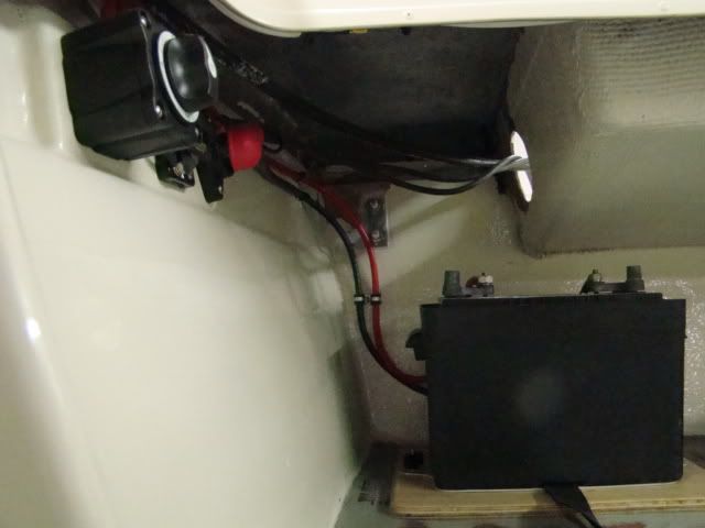
Battery
The main circuits consist of the battery, a main battery switch, a main breaker, a ground post and the main engine pos. and neg. cables.
The battery cables are short so I used 6 gauge marine cable to connect the battery to the battery switch and to the main ground post.
I know 6 gauge seems a little small but the run is very short from the starter to the battery and back. Based on all the ampacity recommendations I have researched, 6 gauge should be plenty. Even if the starter locked up the cables should be plenty to carry the current at this distance. The battery is a marine start 550CCA.
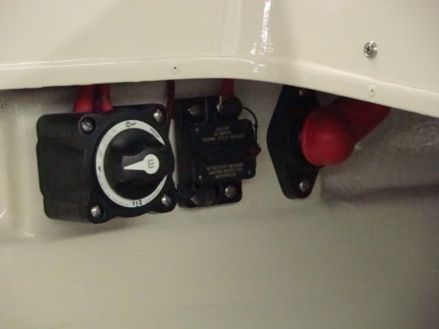
Main Distribution
I used a 1-2-both switch as my main power switch, a 40 amp marine breaker, and a main ground stud to make the connections here. (ignore the color on the ground stud-its ground I promise)
I used a 1-2-both to provide for expansion later. I intend to add a deep cycle battery for trolling and I would like to be able to switch to it when I want to.
The switch has three posts, no. 1, no. 2 and common. I used the number one post for the battery positive making the start battery number 1. All the loads are connected to the common post. When switched to number 1, the start battery powers everything including the engine. When in the off position, the battery is completely isolated.
Also connected to the battery switch common post is the positive cable that feeds the engine and a smaller 8 gauge jumper to the main circuit breaker that feeds the accessory fuse panel mounted under the dash.

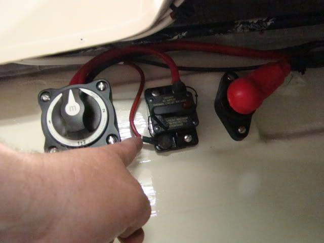
The 8 gauge that feeds the breaker is really overkill in terms of size. I used it because I had it laying around. (also marine) 10 gauge would really be plenty for this little jumper. The breaker I used is a 40 amp resetable with a button that can be used to open (turn off) the breaker. This also acts as my main power switch to isolate all the accessory loads in the event of a problem. These breakers are also marine rated. The 40 amp rating is plenty to provide for the loads on the fuse panel. It is also a low enough amp rating to protect the main power wire in the event it has a short. tip- always rate breakers and fuses under the current rating of the wire at a given length and slightly over the total current needed to power all the consumers on the circuit. (total fuse panel load 30 A, 10 gauge marine cable at 12 feet 60 A= 40 A breaker)
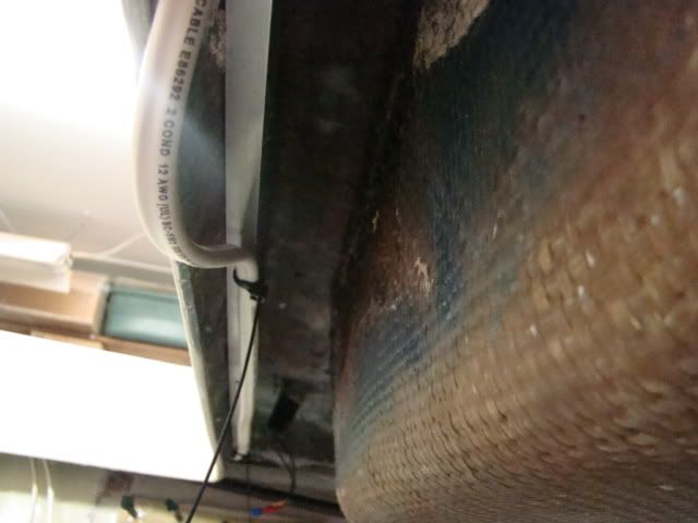
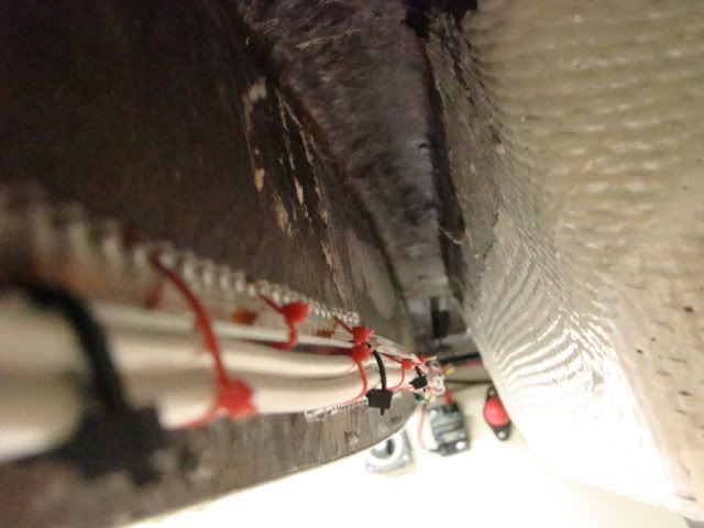
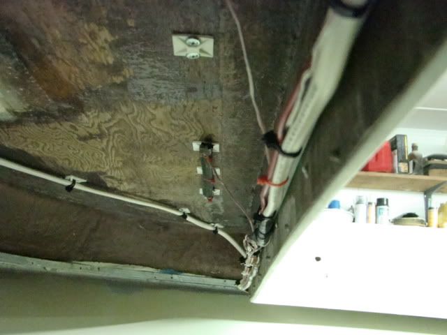
Coming out of the breaker you can see the 10 gauge positive feed that goes to the main fuse panel mounted forward under the dash. Just behind and above you will notice the black ground that connects at the ground stud. The ground also travels forward to a ground buss bar also under the dash. It is duplex wire. (two wires in one jacket)
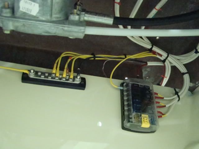
Accessory Distribution
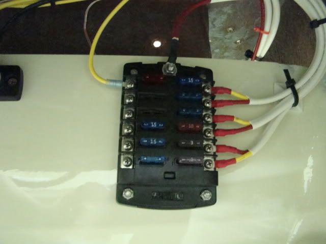
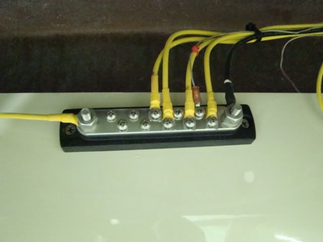
At the other end of the 10 gauge duplex wire is the fuse panel and the ground buss under the dash. I mounted these under the dash because it is a good place to access the fuses and it provides a short run to the switch panel on the dash. (pay no attention to the color code, I had lots of duplex wire so I used it)
If you look closely you can see the 10 gauge red positive in the top feeding the fuse panel and the black negative connected to the buss bar. The fuse panel is a quality unit from Blue Sea systems. It uses standard blade type fuses. It provides 12 circuits in a compact panel and the fuses are readily available. (cover removed)


")