Hi guys, I?m hoping someone will be able to offer me some sound advice with the wiring of my Volvo Penta AQ 151B.
Last year we took the engine out of the boat, following suspected water damage, stripped it down and rebuilt it in the garage. At the time we marked all of the wiring to be reconnected the same. However, rather than putting the engine back in the boat to test it we thought it was best to do it in the garage and that we would be able to by-pass most of the wiring as not being required.
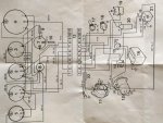
Using the wiring diagram from the workshop manual we tried to work out which wires would be necessary to get her fired up, so basically the start motor and the coil. However, at some point in time, I think the original distributor has been replaced with an electronically converted distributor as the wiring diagram vs our notes start to differ.
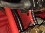
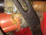
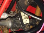
As you will see from the pictures there are 2 small spade connectors on the side of the distributor which connect to the 2 small spades on the reverse of the resistor (my notes don?t confirm which way round these connect, we presumed Left with Left and Right with Right??). The connector which clips on to the top of the Resistor consists of 3 wires ? a black wire which connects to the positive side of the coil, a green wire to the negative side of the coil and 3[SUP]rd[/SUP] brown wire which is earthed (not sure why these colours or in this order but that?s how they were taken off). We have also presumed that the metal bracket holding the coil in place acts as its earth.
So, as per the diagram, the only thing we believed to be missing to provide power to the coil to provide a spark was the wire from the ignition, which we simply fed a wire directly from the positive side of the battery to the positive side of the coil. As per the diagram the negative side of the coil connects to the Tachometer, but we have left this disconnected.
The starter motor turned over without issue but we failed to get a spark and the coil soon got very hot so we disconnected the circuit. We tried the wires between the distributor and the resister the other way round but again this resulted in no spark.
We tested both the Resistor and the coil with a reader to check we had current running through them. The resistor confirmed fine. The coil did only when the wire from the batter was disconnected, when connected there was no reading at all.
I?m hoping this is something simple (and more than likely something stupid we are doing) but any guidance and help you can offer would be greatly appreciated.
[FONT="]Thanks Steve[/FONT]
Last year we took the engine out of the boat, following suspected water damage, stripped it down and rebuilt it in the garage. At the time we marked all of the wiring to be reconnected the same. However, rather than putting the engine back in the boat to test it we thought it was best to do it in the garage and that we would be able to by-pass most of the wiring as not being required.
Using the wiring diagram from the workshop manual we tried to work out which wires would be necessary to get her fired up, so basically the start motor and the coil. However, at some point in time, I think the original distributor has been replaced with an electronically converted distributor as the wiring diagram vs our notes start to differ.
As you will see from the pictures there are 2 small spade connectors on the side of the distributor which connect to the 2 small spades on the reverse of the resistor (my notes don?t confirm which way round these connect, we presumed Left with Left and Right with Right??). The connector which clips on to the top of the Resistor consists of 3 wires ? a black wire which connects to the positive side of the coil, a green wire to the negative side of the coil and 3[SUP]rd[/SUP] brown wire which is earthed (not sure why these colours or in this order but that?s how they were taken off). We have also presumed that the metal bracket holding the coil in place acts as its earth.
So, as per the diagram, the only thing we believed to be missing to provide power to the coil to provide a spark was the wire from the ignition, which we simply fed a wire directly from the positive side of the battery to the positive side of the coil. As per the diagram the negative side of the coil connects to the Tachometer, but we have left this disconnected.
The starter motor turned over without issue but we failed to get a spark and the coil soon got very hot so we disconnected the circuit. We tried the wires between the distributor and the resister the other way round but again this resulted in no spark.
We tested both the Resistor and the coil with a reader to check we had current running through them. The resistor confirmed fine. The coil did only when the wire from the batter was disconnected, when connected there was no reading at all.
I?m hoping this is something simple (and more than likely something stupid we are doing) but any guidance and help you can offer would be greatly appreciated.
[FONT="]Thanks Steve[/FONT]