What happened to the beeper

alldodge

Moderator
Staff member
Joined
Mar 8, 2009
Messages
42,892
Talking about my Formula with the 502. Originally had a MEFI-1 and a direct connection (tan/Blue) from the warning horn (beeper) to the Temp and oil pressure switches and the drive lube bottle. When switch closed the horn would sound.

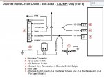
Today, up graded to the MEFI-3 and now all these same switches, Drive lube (Tan/Wht), Oil pressure (BK Blue) and Water Temp (Yel) go to the computer. There is another Tan/Wht wire which connects to the Tan/Blu wire on the engine harness connector. This connector on the wiring diagram shows 5 terminals, mine has 2 smaller connectors.

Issue: when the key is turned to on the fuel pump runs for a few seconds, the normal two beep signal is not heard. No beeps or other sounds are heard. With the engine running at idle, I have grounded the lube bottle terminal and the temp sender wire one at a time. No warning horn/beeper is heard. Put my scanner on the engine and no codes. Not seeing codes would be normal for the MEFI-3 per the sheet I have.
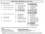
MEFI Codes.jpg

I'm looking for a connection between the switches and the Tan/Blu wire via the Tan/Wht wire coming from the ECM
Also on other motors I have heard the startup beeps come from the engine and not the horn under the helm. Is there a beeper mounted on the engine?
 

Fun Times

Moderator
Staff member
Joined
May 16, 2009
Messages
9,166
You will need to study service manual 23 starting in section 4E page 413 in boat info and skim through all way up to around 640ish.http://www.boatinfo.no/lib/mercruiser/manuals/mercruiser23.html#/640

The yellow coolant wire/sensor is not a direct part of the "discrete" audio waning horn system....So it don't work quite the same way as the oil bottle and the oil PSI switch not to be confused with the oil pressure sender to the oil gauge. You should have 2 blue wires that monitor the oil system. Dark and Light Blue.

You should need to find away to connect the Tan/White to the Blue/Tan wire that go to the discrete switches (< oil, trans over temp, drive bottle). Then if not already done, connect Dark Green from the ECM to the Tan/Blue to fire up the horn.

Also start with page 5E-92 for testing the audio system, http://www.boatinfo.no/lib/mercruiser/manuals/mercruiser23.html#/684

I do believe there where some differences in the wiring connector harnesses between the "engine" wire harness and the "EFI/MPI" wire harness between the MEFI 1's and 3's so you may have to adapt.
 

alldodge

Moderator
Staff member
Joined
Mar 8, 2009
Messages
42,892
Thanks, I have manual 23 and have been looking at it. I have had both harness replaced, engine and Fuel injection with MEFI-3. The difference I have yet to be able to determine is the engine to MPI connector. Manual 23 shows one connector and there is a different number of wires being shown. As you say guess I'm going to need to trace some wires, sure wish I knew this while the engine was out of the boat :facepalm:

mpi.jpg
 

alldodge

Moderator
Staff member
Joined
Mar 8, 2009
Messages
42,892
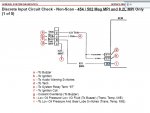
Well lets retry this with more info. Accomplished some tracing and ringing out of wiring and I might be getting close to the answer. If I understand it correctly there are two different MEFI3 modules. The early modules used pin J1-4 or J1-6 and may have been connected together internally to send signal to ECM, later modules used only J1-6. In looking at my wiring harness connector it does not have a wire on J1-6 but does have one on J1-4.

So still guessing here, the ECM and harness do not match. Wondering if the pin can be moved from 6 to 4, or I need a jumper. Sure don't want to damage the ECM but would sure like my alarm to work

Slide2.JPG

Slide1.JPG
 

Fun Times

Moderator
Staff member
Joined
May 16, 2009
Messages
9,166
To bad you don't still have your old wiring harness laying around someplace?

Since it seems you may have the wiring harness with a Tan/White wire on the engine side, it sort of seems like you may have the 7.4 engine model harness.. Not the 454, etc. that used the Tan engine wire. < Just guessing at this point so don't hold me to that..;):)

The 7.4 only you found in the manual, is that the 7.4/L29 engine model or the 7.4 that looks similar to a 454/502 engine design? L29 is much different when it comes to EFI stuff vs the 454, etc.

Since it seems you may have the brown wire going to the J4 right now and it's not working then switching it to the J6 would be the next valid test. No jumping should be required and I would not do that. Just switch them and maybe for the heck of it try comparing check sum numbers to see what ECM you really have. Here's some good info of how to compare numbers and how to switch from J4 to J6. Notice it says switch/change and not jump wires? That should help ensure your question for you.;) http://www.boatfix.com/merc/bullet/97/97_21.PDF

http://www.boatfix.com/merc/bullet/99/99_03.PDF

Good luck.
 
Last edited:

alldodge

Moderator
Staff member
Joined
Mar 8, 2009
Messages
42,892
Thanks FT will have a look

I do have my old harness but it was for a MEFI-1, when the engine was built I asked to change to the 3 figuring there are more of them. Starting to look at MEFI burn software to save the tune program incase something does happen. This is if the builder did not password the tune.

Edit: just looked at it, this is for a MEFI-1 which was my old ECM
 
Last edited:

achris

More fish than mountain goat
Joined
May 19, 2004
Messages
27,468
(Edit: removed)..... Ignore me.
 
Last edited:

alldodge

Moderator
Staff member
Joined
Mar 8, 2009
Messages
42,892
Thanks and I agree, the old system worked fine. Did check the wiring and have power to the beeper/buzzer and as you say, before the sensors supplied the ground and it would turn on. The MEFI3 senses the fault and then applies a ground to turn it on. I rang out the wires so the only thing that I can think of is the wire going to the wrong pin.

Worst comes to worst I can disconnect the feeds going to the ECM and attach them direct to the switches as they were before. Only issue I can see is if it goes off there will be no code thrown, but then again don't know if the ECM needs the 12V being present for another reason
 

achris

More fish than mountain goat
Joined
May 19, 2004
Messages
27,468
If you're not sure which pin is the ground for the alarm, then use an LED (with a resistor wired in series of course) as a test light. Connect the -side of the LED to ground and then put the + end to the pin you wish to check. Ground (create an alarm condition) on one of the sensors. If the LED lights, you found your pin.

The reason to use an LED as opposed to a normal 'test light' is because the LED with the resistor will only draw 20mA. A 'normal' test light will pull around 500mA, enough to cook a TTL circuit.

Chris.........
 
Top