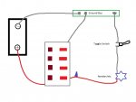
Originally there was a six switch fuse panel that worked just fine but was so low and under the splashwell, I could never see what to turn on or off. So since I was rebuilding the transom, I cut the panel out and am relocating it PLUS I want to add individual toggle switches much higher with labels. So basically, the switches on the panel will always be ON, and feed a toggle switch located elsewhere, for each accessory (livewell aerator, running lights, bilge, etc.). I got more confused when I looked at the diagrams here, so I drew out a simple diagram of what I think will work and I'm asking for verifcation, or a better way. Thanks for you help!

I think it's pretty easy to figure out, battery, fuse/switch panel, bus bar, toggle, accessory. On the panel, there is a red lead and a white lead coming off of it.

I think it's pretty easy to figure out, battery, fuse/switch panel, bus bar, toggle, accessory. On the panel, there is a red lead and a white lead coming off of it.


