Wiring and gauge issue

Mrcleaningguys

Seaman Apprentice
Joined
Aug 7, 2015
Messages
46
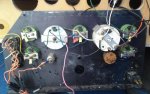
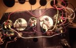
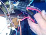
79 century raven. Mercruiser 165hp inline 6. Boat not in the greatest shape. Engine is in good shape though. Picked it up doing a side job for a guy. Needed gauges, switches, floor and needed the wires connected. Bought a dash plate with gauges. Spent days looking for a diagram for my particular instrument harness. Finally found an old mercruiser stern drive repair manual and went to work. I hooked up the wires i knew. Then I noticed I had a voltmeter, but the diagram called for an ammeter. I found a couple threads on here that pertain to my color scheme instrument harness, but they contradict each other. Also found a thread of how to change wiring to accommodate a volt meter. Can someone help me out with the last few wires?

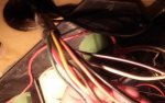
Heavy red- directly to ignition switch "b" terminal?
Yellow- directly to ignition switch "s" terminal?
White- directly to ignition switch "I" terminal?
Red/white- ran to slave solenoid hot terminal?

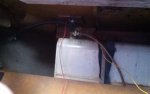
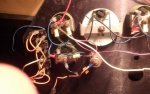
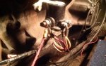
I've got 2 wires coming from gas tank. Red and yellow
Yellow- sending unit?
Red- ran to either fuse block or 12v terminal on gauge?

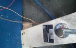
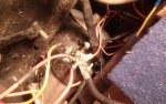
I've got 2 wires coming from the shifter. Red and red.
No idea where these go....

Any help is appreciated. Thank you.
 

Grandad

Lieutenant Commander
Joined
Jun 7, 2011
Messages
1,504
I can't help with the wire colors, but if changing from an ammeter to a voltmeter is troubling you, it's a simple fix, but essential to do before anything will work. An ammeter has very low resistance and is connected in a main positive feeder in series with all your miscellaneous equipment, whereas a voltmeter has a high resistance and is connected in parallel with the main positive feed and main negative. You might be able to simply join the two positives that currently connect to separate terminals on the ammeter by doubling them up on the plus terminal of the voltmeter and then adding a negative from a nearby gauge to the voltmeter's minus terminal. - Grandad
 

Mrcleaningguys

Seaman Apprentice
Joined
Aug 7, 2015
Messages
46
Thanks granddad. I'll double check what I've done. If I posted the diagrams I have, would it give you a better idea of the wire colors?
 

Grandad

Lieutenant Commander
Joined
Jun 7, 2011
Messages
1,504
Thanks granddad. I'll double check what I've done. If I posted the diagrams I have, would it give you a better idea of the wire colors?

I think it would help me or someone else, since it sounds like you have 2 different harnesses that need to be mated or cross-wired. There are standard color conventions such as those from ABYC, but manufacturers may or may not have adopted the colors for their harnesses over a period of time. - Grandad
 

biggjimm

Chief Petty Officer
Joined
Jul 15, 2015
Messages
403
DO NOT hook the wires going to the gas tank to 12v. One probably goes to ground & the other goes to the fuel gauge. I wouldn't want to be any where around if hooking one to 12v all it takes is one spark or for the rheostat to get hot & glow red like a light bulb filament & you probably know the rest of the story. The fuel gauge gets 12v to one side of it & the ground resistance varies going thru the sending unit to ground & that's what makes your gauge work.
 
Joined
Mar 27, 2010
Messages
3,008
I agree with jim... The fuel tank / sending unit does NOT get power to it.

It has a sender wire to the gauge, and a good ground wire to the (-) on the battery. The deck fill if you have one I believe should also have a ground on it.

The fuel level gauge will have:

-switched power from the ignition switch to power the gauge...

-ground on another terminal

-the sender wire from the fuel sender on the tank.. This will NOT have power, it has resistance to ground.. meaning resistance changes as the float level changes in the tank.

-and a separate power wire to the light bulb on the gauge to the (lights switch) if you desire dash lights on the gauges....
 
Last edited:

Mrcleaningguys

Seaman Apprentice
Joined
Aug 7, 2015
Messages
46
DO NOT hook the wires going to the gas tank to 12v. One probably goes to ground & the other goes to the fuel gauge. I wouldn't want to be any where around if hooking one to 12v all it takes is one spark or for the rheostat to get hot & glow red like a light bulb filament & you probably know the rest of the story. The fuel gauge gets 12v to one side of it & the ground resistance varies going thru the sending unit to ground & that's what makes your gauge work.

Yea. When you put it that way, makes sense. Thanks. I guess I just assumed since its red, its hot. Glad I didn't hook it up before asking.
 

Mrcleaningguys

Seaman Apprentice
Joined
Aug 7, 2015
Messages
46
No Title

Ok. Rewired the fuel tank. Didn't have a pink wire for the sending unit, and the yellow wire was in pretty bad shape so I replaced with a distinct blue/white striped wire which I believe was originally part of a power trim harness. Also replaced those RED ground wires. They're now black. No confusion......

I got the engine to turn over but no power to gauges. I hooked the Heavy Red up to"b" terminal and hooked White up to"I" terminal of ignition switch. Yellow was hooked to"s" terminal. I originally only hooked the Red and White wires up to see if I could get power to gauges but tried cranking the motor over for sh*ts and giggles. It turned over but I noticed a little smoke coming from the ignition switch. The White wire was HOT HOT HOT. I took off the White wire and moved the Red wire over to the "I" terminal. Engine turned over again but no power to gauges. Put White on "b" terminal with Red on "I" terminal and got sparks. Any ideas what's wrong?

Plethora of pictures upcoming......
 

Attachments

  • photo227826.jpg
    photo227826.jpg
    59 KB · Views: 0
  • photo227829.jpg
    photo227829.jpg
    58.5 KB · Views: 1
  • photo227845.png
    photo227845.png
    816.9 KB · Views: 1
  • photo227846.png
    photo227846.png
    846.5 KB · Views: 1
  • photo227933.jpg
    photo227933.jpg
    34.7 KB · Views: 1
  • photo227934.jpg
    photo227934.jpg
    62.4 KB · Views: 0
  • photo227935.jpg
    photo227935.jpg
    54.9 KB · Views: 0
  • photo227938.jpg
    photo227938.jpg
    68.4 KB · Views: 0
  • photo227939.jpg
    photo227939.jpg
    52.2 KB · Views: 0
  • photo227940.jpg
    photo227940.jpg
    58.3 KB · Views: 0
  • photo227941.jpg
    photo227941.jpg
    51.9 KB · Views: 1
  • photo227943.jpg
    photo227943.jpg
    63.9 KB · Views: 1
  • photo227944.jpg
    photo227944.jpg
    27.4 KB · Views: 1
  • photo227945.jpg
    photo227945.jpg
    42.3 KB · Views: 0
  • photo227946.jpg
    photo227946.jpg
    69.3 KB · Views: 0
  • photo227947.jpg
    photo227947.jpg
    67.5 KB · Views: 0
  • photo227948.jpg
    photo227948.jpg
    116.4 KB · Views: 0
  • photo227949.jpg
    photo227949.jpg
    153.2 KB · Views: 0
  • photo227951.jpg
    photo227951.jpg
    126 KB · Views: 0
  • photo227952.jpg
    photo227952.jpg
    104.6 KB · Views: 1

Mrcleaningguys

Seaman Apprentice
Joined
Aug 7, 2015
Messages
46
No Title
 

Attachments

  • photo227953.jpg
    photo227953.jpg
    105 KB · Views: 0
  • photo227954.jpg
    photo227954.jpg
    96.7 KB · Views: 0
  • photo227955.jpg
    photo227955.jpg
    89.6 KB · Views: 0
  • photo227956.jpg
    photo227956.jpg
    89 KB · Views: 0
  • photo227957.jpg
    photo227957.jpg
    95.7 KB · Views: 0
  • photo227958.jpg
    photo227958.jpg
    7.4 KB · Views: 0
Joined
Mar 27, 2010
Messages
3,008
Sounds like you have a short somewhere on that white wire.... it is touching ground. Could be at the dash area or at the engine area. The ignition wire is going to feed your gauges, alternator, coil, electric choke.

You have a test light? If not a digital multi meter?

clamp the wire from the test light to (+) on the battery or a wire with battery power on it... and touch the test light to your white wire see if it lights up.... meaning the white wire is connected to ground. IF it does, you have to begin removing things connected to that white wire until it no longer lights up.
 

Mrcleaningguys

Seaman Apprentice
Joined
Aug 7, 2015
Messages
46
PROBLEM SOLVED! If you ever use the edited instrument diagram to convert ammeter to voltmeter, do not hook white up to voltmeter negative. That's where the ground was coming from. And I knew it, but just assumed it must be that way for a reason. The ammeter gets 2 hots and I still don't even fully understand that, but that is for another discussion.
Anyways, removed white, hooked directly to ignition switch. Used a terminal splitter and ran a purple 12v to the same terminal. Problem solved.

Thank you everyone for your responses. Especially concerning the fuel tank. Truly means a lot. I'm an oil change away from firing her up......
 
Last edited:
Top