Wiring older 3 wire Johnson Tilt Trim

Lentine95

Seaman
Joined
Aug 20, 2016
Messages
56
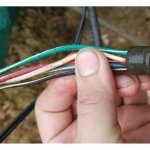
Hey all, looking to wire up the Tilt Trim on my 1977 Johnson 200, my boat use to have a 1989 Evinrude 200 on it. The previous motor had its Tilt Trim wired to a switch on the center console and the wiring is still there, but it had 5 wires running from it and it plugged into the 1989 motor.

Wires- (Green/white, blue/white, red/white, black/white, white) both black/white,and white weren't connected to anything, but still worked

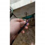
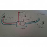
Now the 1977 has only 3 wires coming from the Tilt Trim, and was wondering if I could wire it up like the diagram I drew. Saw some pics online of how should be done and just wanted to double check. But my one question is the ground. I saw that I should ground black wire from tilt trim to the motor itself, and also the negative from battery. But, I also saw that I should connect them to solenoid. Don't know if both work or should do one over the other.
 

Attachments

  • photo260082.jpg
    photo260082.jpg
    30 KB · Views: 94
  • photo260083.jpg
    photo260083.jpg
    41.5 KB · Views: 100
  • photo260084.jpg
    photo260084.jpg
    31.5 KB · Views: 139

Strangeleak

Seaman
Joined
Jan 20, 2017
Messages
55
The '89 actually only has a 2 wire motor, blue up and green down with 2 relays. Both relays are grounded when at rest. Red power on blue will travel through the motor and ground on the green relay and vice versa. The other two wires were for tilt/trim gauge.

The 77 should only need switched power to blue and green. The black should always be grounded. You should have two relays though, not one. The only concern I see in your drawing is the green wire bypassing the relay. The motor draws too many amps for a small gauge wire and simple switch. Unless that's 10ga wire and a 30amp switch. Even then thats a lot of current to route through your boat without a fuse/breaker.
 

Strangeleak

Seaman
Joined
Jan 20, 2017
Messages
55
I was wrong. I just found a photo from another manual. The green wire does bypass the relay. Maybe the current load on the circuit is less on the down function. I still think it's an antiquated design. Upgrading to the 2 relay design delivers more power and does it much safer.
 
Last edited:

Lentine95

Seaman
Joined
Aug 20, 2016
Messages
56
Thanks, actually wired it up today just to give it a test and it worked out good how I drew it up. Also, the wire on motor is 10ga and wire coming from the center console switch is 14ga.

Read online that the down function does require less amps to move it since of gravity helping with bringing it down. So maybe that's why the bypass, but probably wouldnt be bad idea to run two solenoids, one for up (blue), and one for down (green).

Think I should have some inline fuses with this set up? Also, should I ground the black wire from trim tilt, and Negative from battery to the engine block? Right now they're on one of the small terminals on the solenoid
 

Strangeleak

Seaman
Joined
Jan 20, 2017
Messages
55
The ampacity of the 14ga wire is 15 amps so I would install a 15a fuse on the red wire to the switch. If the fuse blows when the circuit is live, you need to upgrade the wiring.

The Negative from the battery should already be grounded to the block through the starter and other various places in the harness. As long as the wire is of adequate gauge all the way back to the battery, then where you ground it is up to you. Ground is ground.
 
Top