Yet Another Trim Gauge - Wiring Diagram - Question

TozerBGood

Cadet
Joined
Aug 11, 2010
Messages
6
Newbie to the forum here. I searched quite a bit but haven't been able to find my answer. I suspect the question's been asked a 1000 times, but here goes anyways.

I recently got a used '89 Bluewater 18' Eagle.

The previous owner had removed his fishfinder, and in the process I discovered he had inadvertantly pulled some of the wiring off of the volt meter, fuel gauge, and trim guage. I think I got the fuel guage and volt meter figured out, but all the wires are pulled off of the trim gauge, and it has me stumped.

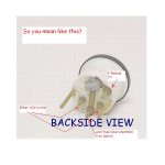
I can't spot any "I" or "S" or anything on the back of it, but it essentially looks just like this.

4483-2-lg.jpg

4483-1-lg.jpg


Can anyone tell me what goes where?

I'm assuming there's 2 wires from the sending unit and then red +12v and black ground? What colors are the wires from sending unit usually? Which terminals do they go on...etc etc.
 

TozerBGood

Cadet
Joined
Aug 11, 2010
Messages
6
Re: Yet Another Trim Gauge - Wiring Diagram - Question

I found this following infor searching the web. It mentions trim senders on Alpha units ( which my boat has an Alpha sterdrive)

But it still doesn't contain what I want to know.

Replacing Your Trim Limit and Trim Position Senders

Alpha's and Bravo's have two Trim Senders.

They are mounted on either side of the Gimbal Ring.
One sender is for the Trim Gauge and the other sender is for the Trim Limit.

The Trim Limit Switch is mounted on the port side and the Trim Position Switch is mounted on the starboard side.

The switches are prone to damage from water intrusion. Water enters the switch and ruins the contacts. The wires tend to soften and/or rot with age and water leaks into the switch through the wires.

This is why the new switches are sold with the new wires are already attached at the factory. Always replace the wires when replacing the switches.

Symptoms
The Trim Position Switch operates the Trim Gauge.
When the Trim Position Switch fails, the gauge usually pegs to "full up".

The Trim Limit Switch prevents the driver from 'over-trimming" the outdrive while under way.
It is an important limiting feature which prevents damage to the drive and/or loss of control of the vessel.
Trimming the drive unit up too high while the boat is running can cause serious damage and/or injury.
When this switch fails, the TRIM BUTTON does not work. Only the TRAILER BUTTON will work.

When one switch fails, you will end up replacing both switches. This is because the switches are sold in sets of two. Both the Trim Limit and the Trim Sender switches are sold together as a pair.

Replacing the switches requires removal of the drive and bell housing.
These are the same procedures for replacing the Ujoint Bellows.

Replacing Your Alpha One Bellows
Replacing Your Alpha Gen II Bellows
Replacing Your Bravo Bellows

Trim Sender Units
The trim senders are no longer sold individually.
The Port switch is the Trim Limit Switch. This limits how far up the drive will trim.
The Starboard switch is the Trim Level Sender switch. This sends a signal to the trim gauge.

If one or the other malfunctions, you will need to get the entire Kit.
The Kits comes with both senders. The senders are pre-wired from the factory
with new wires.
Mercruiser did this because bad wires were the leading cause for switch failure.


805320A03 Single Station Trim Sender Kit $99.92


If you have Dual Stations (for example, a gauge below and a gauge on the bridge),
You will also need to purchase the Dual Station sender from below.

805130A6 Dual Station Trim Sender Kit $79.25


Purchase Manuals for switch replacement procedures.

You will also need a Hing Pin Tool to remove the bell housing.
 

TozerBGood

Cadet
Joined
Aug 11, 2010
Messages
6
Re: Yet Another Trim Gauge - Wiring Diagram - Question

ttt
Hmmm....no interest or help?
(Felix would open his bag of tricks at this point)
 

Silvertip

Supreme Mariner
Joined
Sep 22, 2003
Messages
28,771
Re: Yet Another Trim Gauge - Wiring Diagram - Question

Look at the back of the gauge again. "+" is =12 volts when the key is on. "-" is ground. The terminal on your gauge with the copper strip going up to the light is the +12 volt feed for the internal light. It comes from the NAV/ANCHOR switch. The terminal that's left would be the "S" terminal.
 

TozerBGood

Cadet
Joined
Aug 11, 2010
Messages
6
Re: Yet Another Trim Gauge - Wiring Diagram - Question

Look at the back of the gauge again. "+" is =12 volts when the key is on. "-" is ground. The terminal on your gauge with the copper strip going up to the light is the +12 volt feed for the internal light. It comes from the NAV/ANCHOR switch. The terminal that's left would be the "S" terminal.

Like this (see attached sketch)? I don't believe there is an Anchor switch. I'm confused. I thought it was either a trim limit and trim sensor on the sterndrive? (that is 1 having a discrete output, and one having a continuous position indication).
 

Attachments

  • Trim Gauge.jpg
    Trim Gauge.jpg
    29.6 KB · Views: 8

RicMic

Chief Petty Officer
Joined
May 14, 2010
Messages
431
Re: Yet Another Trim Gauge - Wiring Diagram - Question

The anchor LIGHT switch.
 

Silvertip

Supreme Mariner
Joined
Sep 22, 2003
Messages
28,771
Re: Yet Another Trim Gauge - Wiring Diagram - Question

Let's start over again. Look at the internal light bulb holder at the top of the gauge. The terminal on the right is the ground side of the bulb -- it is NOT the "S" terminal. The copper strip leading down goes to (or comes from) the switch that controls the Navigation and Anchor lights on your boat. If you don't have lights, that terminal can be jumpered to the +12 volt terminal which means the light would be on any time the gauge is active. I can't see the area around the terminals very clearly in the picture but there is definitely a marking on the plastic. Look at those carefully. Since the light must be grounded to work, that terminal is the ground for the gauge. So what you show as the "S" terminal is ground. One of the bottom two terminals is +12 volts and the other is "S" (send). The two long studs are simply used to fasten the "U-bracket" and therefore the guage, to the instrument panel.
 

TozerBGood

Cadet
Joined
Aug 11, 2010
Messages
6
Re: Yet Another Trim Gauge - Wiring Diagram - Question

Ok. I got home from work and pulled the gauges, and you are correct...the poles are labeled but I had to use a magnifying glass to read it (my eyes are getting worse).

Anyways...with your help I think I got it figured out now and it makes perfect sense (now you explained it). The gauges show the I, G, & S but no indication of +12v from Nav Lite, but your excellent help cleared that up.

My gosh you guys must get tired of the same old questions, but I much appreciate it.

Here's a pic of my actual gauges ( which aren't exactly like the pic I got from the web - but close enough).

Fuel%20&%20Trim%20Gauges.bmp


I hope this thread will help someone else. I'm sure there's a 1000 threads, and 1000 newbies for each one. But this one has PICS!
 

TozerBGood

Cadet
Joined
Aug 11, 2010
Messages
6
Re: Yet Another Trim Gauge - Wiring Diagram - Question

There - all put back together and working. Again...thanks for the excellent help.
 
Top