Wiring mess!!

xpmservices

Recruit
Joined
Mar 1, 2015
Messages
5
Hey guys, I got a 1991 Astro boat. Just installed new ignition and everything is running pretty good engine wise. Well none of my accessory switches work( Bilge, Livewells, lights.. nothing) Figured maybe I needed a new master switch or something. I got a new one but when I opened up the switch panel, someone had already been in there and screwed up the wires. Master switch wires were all unhooked and have no clue where anything goes. There are a billion wires under there. I have tried to go through them and figure it out but there are disconnected wires and cut wires everywhere. I am not good with boat wirieing by any means but can do simple wiring Do you think it would be easier to just leave those wires alone and wire in a new fuse/switch panel? Its a pretty aggravating situation...lol... and advise would be helpful. Thanks
 

Silvertip

Supreme Mariner
Joined
Sep 22, 2003
Messages
28,771
What do you hope to gain by installing a new fuse panel since you have no idea where any of the wires go to now?. So save the panel you have. Where wires have been cut that had been attached to switches or the panel, remove those stubs but at least try to match wire colors. That should help put things back as they were. If that isn't possible, then start with one accessory at a time and follow the +12 volt and ground wire back to the switch and the ground buss respectively. Remember, the switch is "after" the fuse panel so the wire will go to the switch then from the switch to the fuse panel. The fuse panel itself has one INPUT power lead that is typically a #10 gauge wire that comes directly from the positive terminal of the battery -- not the ignition switch. There will be a 20 or 30 amp circuit breaker or fuse (depending on wire size) near the battery terminal to protect that line. When you have one accessory working, move on to the next one. Power to the gauges does come from the ignition switch. The back lighting for the gauges comes from the NAV/ANCHOR light switch. This should at least get you started.
 
Joined
Feb 17, 2012
Messages
2,906
its not a mess of wires its just one wire a lot of times that looks like a mess.

Start at the beginning

Battery has a red wire about 10g that is either connected to the battery positive or the a/b dual switch (if installed) it should have a breaker or a 30 amp fuse near where it connects. That goes to the master switch. The other side of the master goes to the fuse panel (may not be fuses but a block of little silver cans that are joined together under the dash, these are self reset breakers for the aux switchs). Once you get that far and confirm on a volt meter that you have power post back whats going on.
 

xpmservices

Recruit
Joined
Mar 1, 2015
Messages
5
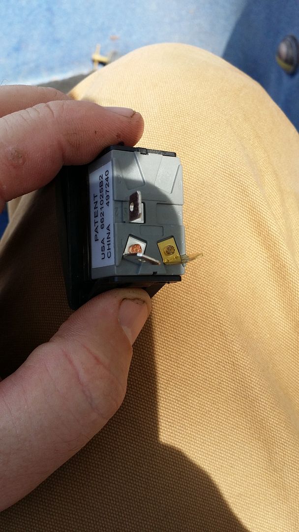
Hey guys thanks for the response.. Everything is hooked up at the battery.. Took a volt meter to all my switches and they are all getting power... I did notice that the ground wire on that is daisy chained to all my switches is going to no where... just a pair wire It ends near the master switch... could that be my issue??? My next question is on my new switches i have gold and silver terminals.. How do I know which ones are ground aand positive? most have 1 silver and the rest are gold.. I dont have much to go off of cause the switches I am replacing where already unhooked. I was assuming silver is ground but I am not good with this stuff. below is a pic of the new switch, old switch was a 3 terminal as well.

 
Last edited:

gm280

Supreme Mariner
Joined
Jun 26, 2011
Messages
14,605
You stated that you have no problems with simple wiring issues. Well what you really have is a lot of simple wiring issues. Each wire has a place it comes from and goes too. So instead of seeing a total huge rats nest, start with one wire and track it to where it came from and where it goes too. And before you know it, you will understand the entire wiring mess. And as you start working on tracking each wire, mark them as to what they are for as you figure them out. And even draw them on a piece of paper as well. And when you are finished, you will have all of them marked AND a wiring schematic to use later on if need be. Wiring looks overwhelming until you look at it as simple little circuits that just happen to be in the same area... Bundle and wire tie them in nice bundles and it wouldn't be a rats nest next time. And lastly, take you time. Don't hurry and make matters worst. Clean each connector when working on that circuit. It really is that simple... JMHO!
 

xpmservices

Recruit
Joined
Mar 1, 2015
Messages
5
You stated that you have no problems with simple wiring issues. Well what you really have is a lot of simple wiring issues. Each wire has a place it comes from and goes too. So instead of seeing a total huge rats nest, start with one wire and track it to where it came from and where it goes too. And before you know it, you will understand the entire wiring mess. And as you start working on tracking each wire, mark them as to what they are for as you figure them out. And even draw them on a piece of paper as well. And when you are finished, you will have all of them marked AND a wiring schematic to use later on if need be. Wiring looks overwhelming until you look at it as simple little circuits that just happen to be in the same area... Bundle and wire tie them in nice bundles and it wouldn't be a rats nest next time. And lastly, take you time. Don't hurry and make matters worst. Clean each connector when working on that circuit. It really is that simple... JMHO!

Thanks for responding GM... I am working with it and trying to figure it out... all though you didnt answer any of my questions above about the switch...lol... I am getting power to my switchs now... I took the end of the ground that wasnt hooked up and ran it to the Negative on the battery to test it out and all my swtiches are getting power. I am replacing most of my rocker switches, some have 5 wires going to them. Only thing I havent figured out is which one is negative gold or silver on the switch?
 

Grandad

Lieutenant Commander
Joined
Jun 7, 2011
Messages
1,504
My next question is on my new switches i have gold and silver terminals.. How do I know which ones are ground aand positive? most have 1 silver and the rest are gold..]
I can't say for certain, but searching the US Patent number from the picture, you have a lighted rocker switch. Just by the physical placement, I would expect that terminal 2 should be positive, terminal 1 would go to the device you're switching and the brass colored terminal would be negative as required for the LED. You need to confirm this using an Ohmmeter, being careful to observe the polarity of your test leads, as the LED may permit current flow for your meter in one direction only. - Grandad
 

xpmservices

Recruit
Joined
Mar 1, 2015
Messages
5
I can't say for certain, but searching the US Patent number from the picture, you have a lighted rocker switch. Just by the physical placement, I would expect that terminal 2 should be positive, terminal 1 would go to the device you're switching and the brass colored terminal would be negative as required for the LED. You need to confirm this using an Ohmmeter, being careful to observe the polarity of your test leads, as the LED may permit current flow for your meter in one direction only. - Grandad

Yeah that particular switch is going to be my master switch, that one wont have any particular devices run to it, it will turn on and off the current to the rest of the switches. it is hooked up right now with the gold being a ground and the other two being positive. The switches seem to all be working, except the livewell switches. I got some new ones and they turn on the live well but they done lock into place, guess the wrong kind of rocker switch for them. They sent me ones that soon as you let them go it goes right back to the off position unless its a broken switch.
 
Last edited:

Grandad

Lieutenant Commander
Joined
Jun 7, 2011
Messages
1,504
The switches seem to all be working, except the livewell switches. I got some new ones and they turn on the live well but they done lock into place, guess the wrong kind of rocker switch for them. They sent me ones that soon as you let them go it goes right back to the off position unless its a broken switch.
It sounds like they are only "momentary" switches that you might use to initiate a start in a circuit with a timer that seals in and turns the pump on for a period of time. They normally control a timer/relay that you likely don't have. - Grandad
 
Top