boxchevyman
Seaman
- Joined
- Mar 16, 2014
- Messages
- 61
1975 85hp Johnson.
Model: 85ESL75E
The battery is only displaying the battery voltage of 12.6v when running or not. The motor runs great. I have a service manual, so i decided to look at the rectifier first. I did a quick test.
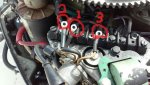
I took the negative MM lead to ground, then went to wire 1,2,3. these are the readings.
wire 1, continuity
wire 2, no continuity
wire 3, continuity
I then reversed the leads and took the positive MM lead to ground, these are my readings,
wire 1, continuity but some resistance
wire 2, no continuity
wire 3, continuity but some resistance
With that information should i assume the rectifier is shot and this is the cause of my system not producing a charge?
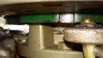
Just for more information i also attached a picture of the the underneath of the flywheel the stator looks ok-ish to me but whatever you guys think?
thanks!
James
Model: 85ESL75E
The battery is only displaying the battery voltage of 12.6v when running or not. The motor runs great. I have a service manual, so i decided to look at the rectifier first. I did a quick test.
I took the negative MM lead to ground, then went to wire 1,2,3. these are the readings.
wire 1, continuity
wire 2, no continuity
wire 3, continuity
I then reversed the leads and took the positive MM lead to ground, these are my readings,
wire 1, continuity but some resistance
wire 2, no continuity
wire 3, continuity but some resistance
With that information should i assume the rectifier is shot and this is the cause of my system not producing a charge?
Just for more information i also attached a picture of the the underneath of the flywheel the stator looks ok-ish to me but whatever you guys think?
thanks!
James