adding a diode (or two) to allow trim gauge to work without ignition

chopsbutcher

Cadet
Joined
May 30, 2013
Messages
6
Just curious if anyone does this or if it causes any concern. My trim switch is hooked directly to power but the gauge is powered by the 'on' setting for the ignition. Rather than turning on the ignition each time I raise/lower the motor, I'd like to be able to see the trim position any time the trim motor runs. So I was thinking I can place a diode in-line from the positive of the trim motor to the positive of the trim gauge? This would provide a power source to the gauge while the trim is active. I'm pretty sure I'd also need a diode between that gauge positive and the 'on' bus so it doesn't accidentally back-power the ignition system.
 

bruceb58

Supreme Mariner
Joined
Mar 5, 2006
Messages
30,620
Seems reasonable but if you really want to see the trim position, why not just turn on the ignition?
 

sam am I

Commander
Joined
Jun 26, 2013
Messages
2,169
No need for diodes...........Just clip the trim gauge's power from the ig side (Purple) and power it with batt.(Red) circuit after the main batt. switch.....Just realize it will use a tad bit of current with the main switch on...........few milliamps.

Before.jpg After.jpg
 
Last edited:

bruceb58

Supreme Mariner
Joined
Mar 5, 2006
Messages
30,620
No need for diodes...........Just clip the trim gauge's power from the ig side (Purple) and power it with batt.(Red) circuit after the main batt. switch.......
And then have your battery go dead!
 

bruceb58

Supreme Mariner
Joined
Mar 5, 2006
Messages
30,620
LOL...well we will let the OP decide if he thinks that is a good idea!
 

sam am I

Commander
Joined
Jun 26, 2013
Messages
2,169
Sure and ty for allowing that, I'm sure he'll appreciate that ....LOL
 
Last edited:

Silvertip

Supreme Mariner
Joined
Sep 22, 2003
Messages
28,771
Unless you cannot see the engine from the helm, engine running or not -- a trim gauge is the most useless gauge on a boat. Can't see one good reason to do this. But - since you asked, run a diode from the up and down side of the trim switch to the "I" terminal on the gauge. Now the gauge should read when the trim switch is actuated.
 

chopsbutcher

Cadet
Joined
May 30, 2013
Messages
6
Well isn't this the active board tonight! It's an I/O, so there is no line-of-sight to the engine from the helm. Thanks for the schematic Sam I Am! I considered powering it straight off batt + but I have no main battery switch and would prefer not to have a constant (although admittedly tiny) draw.
I'll probably end up leaving it as-is and turning on the switch. Just thought it would be a neat idea and curious if anyone had experience with it.
Thanks to all who commented!
 

sam am I

Commander
Joined
Jun 26, 2013
Messages
2,169
Quite welcome, just quick napkin scratches w a bit assumptions on the boat. Takes the guess work out though........

Your idea is neat, I like it and your thinking outside the box, it's quite founded IMO, similar to having a steering position indicator, nice to know where things are at a glance, engine/key on running or not, esp with a system that has power to the trim motors w/o key on, running blind (or being able to, is this stock?) isn't too good and isn't a good design IMO............No main switch? Wow, hmmmm, ummmm, I'd definitely consider installing main batt. switch in the future.....Dog butts/kids sitting/bumping on switches controlling outdrives on the trailer and at the ramp? Stranger things have happened......


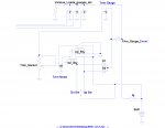
The work around? Not too complicated at all!!.........A standard SPDT relay (prevents other loads from coming on with the trim gauge) and a OR'ing diode config (two diodes, D1, D2 wired as shown) with the trim switch up/dn relay control signal will do what ya wanted w/o a main switch.........It's basically Silver's idea, with the key still off, the gauge will work only when either the up or down is used/bumped. It'll work as normal when the key is on/motor running. You could use a push button tied to the batt + to activate the relay when needed and skip the diodes as an additional option.


After_rev1.jpg


Not sure I can see/in-vision the config as suggested where just a diode/s would be installed and still prevents the other ig. loads from being turned on at same time. And, in addition to leaving the gauge tied to the ig. so it works with motor running (sketch would help).
 
Last edited:

chopsbutcher

Cadet
Joined
May 30, 2013
Messages
6
If we can ignore the negativity and get back on topic I am curious, Sam I Am, as to why the suggestion for the relay? I think I could add in another diode to the circuit to prevent back-powering other devices. We were having so much fun with diodes, why introduce a mechanical point-of-failure?


trim_gauge.jpg
 

Attachments

  • trim_gauge.jpg
    trim_gauge.jpg
    211.3 KB · Views: 0
Top