Testing Trim Sensors

rickasbury

Senior Chief Petty Officer
Joined
Jul 13, 2011
Messages
799
In a "second" phase of a gimbal restoration as I would now call it...I had done my bellows on my Bravo III and put back together. My trim worked fine before I pulled it apart to do the bellows but when I re installed, the trim went up and down fine but I had to register on my gauge and it did not want to seem to respond to the one that controls the max up position. I would tell you also, when I was trying to get the bell housing off, I recall one of the sensors getting all bound up as it was hanging loose and got jambed in between the bell housing and the outer gimbal so got a bit crushed- no visible damage however. So I have them out and off of the boat, is there a way to test them?
 

alldodge

Moderator
Staff member
Joined
Mar 8, 2009
Messages
43,239
The trim gauge sender (starboard side), connect an ohm meter on the leads and rotate the unit and you should see resistance increase and decrease smoothly as it is turned.

The trim switch, connect an ohm meter on the leads and rotate the unit. It should go from zero ohms to to open connection. Rotate back and zero ohms again (on then off)
 

rickasbury

Senior Chief Petty Officer
Joined
Jul 13, 2011
Messages
799
OK, talk to me like a four year old.....I have my meter, what do I set it on? Also, am I using the OHM
 

alldodge

Moderator
Staff member
Joined
Mar 8, 2009
Messages
43,239
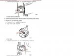
Set it on like 2K scale, then connect the two leads to the two wires going to either the trim limit or trim sender. Match the mark as seen in the pick below to start with. Then turn the inner piece while keeping the outer body stationary.

If your doing the limit the ohm will read zero ohms, and as its turned it will go to infinity (open circuit), and go back to zero ohms if rotated back

If your doing the gauge sender, you will see the ohms get greater in one direction and less when its rotated back

Presentation1.jpg
 

rickasbury

Senior Chief Petty Officer
Joined
Jul 13, 2011
Messages
799
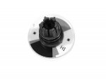
Dodge- are you accounting for the fact I'm holding these in my hand and they are not hooked up to anything? I'm not sure that my gauge is working...when I set it on continuity, should it go to 1? When I set it on the 20K Ohm, it really does not do anything...and then it starts running up and down on the display, does not appear to do anything when I turn them. Also, what goes bad on these? I see you can replace the rotors for 21 bucks...I pulled one apart, it has not gotten wet. Is there anyway to test the base part? I see two brush like pieces...should there be continuity between those? Either I'm not testing correctly or I don't have them set up to test correctly. They worked before I tore it down to do the bellows the first go around....I'm assuming at this point either you work on boats for a living or used to? You know to much to be a back yard get him self in trouble person like me.... rotor.jpg
 

alldodge

Moderator
Staff member
Joined
Mar 8, 2009
Messages
43,239
Dodge- are you accounting for the fact I'm holding these in my hand and they are not hooked up to anything?

For the most part yes

I'm not sure that my gauge is working...when I set it on continuity, should it go to 1? When I set it on the 20K Ohm, it really does not do anything...and then it starts running up and down on the display, does not appear to do anything when I turn them.

Don't know the going to 1 comment. If you take an ohm meter probes and connect the two leads together, the meter should read zero ohms. If the meter probes are disconnected from each other the meter shows max scale ohms or infinity.

There are some youtube things out there, but your limit switch is just like a light switch, it turns on and off only. So the limit switch has 2 leads coming from it. If the meter is connected to it, there is a point where the contact will open (or stop making connection)

The trim sender is a variable resistor. When its rotated, the resistance increases in one direction and decreases in the opposite direction. The senders can be turned completely 360 but don't do that. The area of connection should be in the 45 to 60 degree range. Also move/rotate it slowly

The moving up and down the display may be correct but unsure of the comment
 

rickasbury

Senior Chief Petty Officer
Joined
Jul 13, 2011
Messages
799
so, I'm connecting the meter to the end of the leads to do the tests? The leads are not plugged into anything on the boat. I would think the leads would have to be plugged in to "test the circuit"? I know nothing about electrical stuff...I can follow directions but....
 

alldodge

Moderator
Staff member
Joined
Mar 8, 2009
Messages
43,239
so, I'm connecting the meter to the end of the leads to do the tests? The leads are not plugged into anything on the boat

Yes, correct, just the meter
 

rickasbury

Senior Chief Petty Officer
Joined
Jul 13, 2011
Messages
799
Then either the gauge is not reading correctly or they are bad- they were working fine before I did the bellows and when I re installed, did not seem to work. I wonder what could have happened in between? I will borrow a gauge from my neighbor, I don't have much faith in the one I have....thx
 

rickasbury

Senior Chief Petty Officer
Joined
Jul 13, 2011
Messages
799
I did get a new meter...the limit switch as I rotate it when it gets to a certain area numbers will pop up and then as I turn it, back to one. so I assume that switch may be working. The sender does nothing. I wonder what happened? They worked fine before they broke, just not sure what would have broken them.....yikes.
 

jbuote

Lieutenant Junior Grade
Joined
Aug 17, 2016
Messages
1,001
They worked fine before they broke
I love this!!!
I too have had things working fine before removing, then just not work when re-installed... Never did figure it out..
But this.... I can relate!!
Oh I love it!! :D
 

alldodge

Moderator
Staff member
Joined
Mar 8, 2009
Messages
43,239
What scale is the meter on?

You could take the wire coming from the sender or switch and ground it, then take the wire coming from the gauge and connect it to the other wire on the sender. Turn the key on and move it and watch gauge.
 

rickasbury

Senior Chief Petty Officer
Joined
Jul 13, 2011
Messages
799
Dodge- if you recall, these parts are sitting on my bench! I can turn the key but I don't think that will help! I have a friend that has told me that for checking resistance, they do not have to be hooked up. I don't quite follow that but he is knowledgeable so I will have to go with that. I bought a new meter and got zip. The other was crap anyway....When I did my bellows and re installed, they did not work. The only thing I can think, in the manual it states when installing new one ( and I assume re installing old ones!) to disconnect the battery before installing which I did not do. Other than that, I can't think of anything....
 

alldodge

Moderator
Staff member
Joined
Mar 8, 2009
Messages
43,239
Yes, they should be able to be tested with an ohm meter on the bench. It is a variable resistor and show between 80 to about 300 ohms. If you have an auto-ranging meter, it should change scales on its own. If you have a meter that has different settings for the scale it needs to be set close to the 300 ohm setting.

A variable resistor is like a water valve. The more the valve is closed (resistance increases) the less water comes out, the more the valve opens (less resistance) the more water. A variable resistor is used in many things like the radio volume, dimer switch.

If the sender is turned to far it may loose connection.
 

rickasbury

Senior Chief Petty Officer
Joined
Jul 13, 2011
Messages
799
I see them on Ebat for 55 bucks so I think I will stop driving myself crazy on this one- no clue what happened to them but there is no reading on either one of them and they did not work on the boat either all of a sudden. I'm ready to put this sucker back together and get back to boating. I will pull apart the steering pin and look at that, get a new seal for it, clean/prep and paint and get going. Still just takes for ever...
 
Top