shift boot, dry or bellows adhesive...

rickasbury

Master Chief Petty Officer
Joined
Jul 13, 2011
Messages
800
So, my boot has come off 2x....the exhaust bellows is so close I don't think the boot is getting on good at the transom...I did use adhesive which when tackey makes it just that much worse..so ..have it cleaned back up, glue or not?
 

Grub54891

Admiral
Joined
Jun 17, 2012
Messages
6,307
I've always used bellows adhesive. Never had one come off, are you stretching it to tight? It shouldn't be to stretched when the drive is trimmed up.
 

rickasbury

Master Chief Petty Officer
Joined
Jul 13, 2011
Messages
800
Yeah...I got something going on...like I mentioned above that side against the exhaust bellows I may not be getting on good- why is this such a tight fit? Anyway, I got it all cleaned off as best I can get it and will try again am. Should I wait for for it to get tacky or slide it together while it's still a little slippery? I pulled and re installed the motor in this boat and this stupid boot is kicking my butt!
 

harringtondav

Commander
Joined
May 26, 2018
Messages
2,480
I fought the same issue the last time I replaced the exhaust bellows. I think I was gooping on too much adhesive. It stretched loose three times. I pitched the bellows and bought a new one. Then I used BT Doctur's 3M Black Weatherstrip Adhesive--sparingly, and waited for full tackiness. Rock solid now.

The shift cable bellows should also have adhesive. But a common problem is the crimp clamp on the aft end is too tight. The cable should be able to slide in and out. If that clamp is too tight the bellows may over stretch and fail, or pull loose.
 

rickasbury

Master Chief Petty Officer
Joined
Jul 13, 2011
Messages
800
Heck, it does not slide in and out with nothing on! I used a zip tie but have it off now making this repair.
 

rickasbury

Master Chief Petty Officer
Joined
Jul 13, 2011
Messages
800
Ok, so after it was cleaned up and taking the exhaust bellows off(will deal with that another time) I was able to slide it on while lightly using the adhesive. So, I start tighting down the clamp and the boot kind of just walks off the nub on the transom. On that post there is a machine surface like to help it secure.. grooves...then it hits a lip and the there is another quarter inch or so of the ruff casting...there is a little lip in the boot- so I slid it on so the lip on the post and the boot touch and then installed the clamp.vitsblike it's tapered and when I do the clamp it just sounded down? There should be a machined Grove for all these rubber parts so the clamp had something to grip- I'm not impressed at all with the design of this transom?
 

achris

More fish than mountain goat
Joined
May 19, 2004
Messages
27,468
What you working on? Alpha One, Alpha One gen II, Bravo?

Chris.........
 

rickasbury

Master Chief Petty Officer
Joined
Jul 13, 2011
Messages
800
sorry...I don't see in my profile where I can put this info...it's a bravo III...also, I put new trim sensor and limit senders on the out drive when I had it pulled off and the engine out....the sensor seems to be working fine but the limit is not...have never adjusted one before...I'm looking on you tube and found one thread....almost looked like when you had it close ( mine was going out to 26" so that mystery is solved) you could move the sensor to dial it in to where you want it, correct? With out actually hitting the trim button on the helm right? Mine is not doing anything....I did have the pump out when to motor is out...the wires from the out drive I verified are connected....I don't recall undoing much on the pump itself.....at least I can use the up and down on the position to keep it from going to high and using the boat this weekend, will just have to be carefull with it. But that is the way it is supposed to work, right? Turn the sender and it will work the pump?

I did a quick look of the wiring at the pump for the limit and it looks to be good...I don't see a real trouble shooting method in the manual for it....and my electrical is not so good.....so I know what the max dimension should be at the limit and then you have the trailer position...how much further out do those rams go for that? I'm not sure it ever worked to be honest...half the time the button would not work and I'd have to hit the trailer to bump it up to trim....seem like the regular up and down is working just not the limit.
 
Last edited:

rickasbury

Master Chief Petty Officer
Joined
Jul 13, 2011
Messages
800
So update from the ramp per above which I can't edit on phone...that dang thing worked itself about halfway off...if I turn the clamp around will it go the other way? This is crazy!
 

scoflaw

Ensign
Joined
Jun 2, 2010
Messages
962
I do all my bellow's dry now just because of what you are seeing. Clean the rubber and mating surface with Gumout carb cleaner. Set it n forget it.
 

fishrdan

Admiral
Joined
Jan 25, 2008
Messages
6,989
Should I wait for for it to get tacky or slide it together while it's still a little slippery?

The adhesive needs to be tacked up, dry to the touch, i let it sit for about 15 minutes before installing the bellows. If the adhesive is wet, it will lubricate the bellows and allow them to slide off.

Tacked up adhesive doesn't like to slide across itself, so you need to apply something to let the bellows slip, PowerTune is a favorite here on the forums, basically something that will lubricate the adhesive, and then dry quickly once the bellows are in place.
 

achris

More fish than mountain goat
Joined
May 19, 2004
Messages
27,468
sorry...I don't see in my profile where I can put this info...
Go to your profile. Click 'Account', about half way down is 'Edit Signature file'..

profile.PNG

it's a bravo III...also, I put new trim sensor and limit senders on the out drive when I had it pulled off and the engine out....the sensor seems to be working fine but the limit is not...have never adjusted one before...I'm looking on you tube and found one thread....almost looked like when you had it close ( mine was going out to 26" so that mystery is solved) you could move the sensor to dial it in to where you want it, correct? With out actually hitting the trim button on the helm right? Mine is not doing anything....I did have the pump out when to motor is out...the wires from the out drive I verified are connected....I don't recall undoing much on the pump itself.....at least I can use the up and down on the position to keep it from going to high and using the boat this weekend, will just have to be careful with it. But that is the way it is supposed to work, right? Turn the sender and it will work the pump?

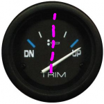
The limit switch is design to allow the UP button to work from the full DOWN position to the position where the trim rams are extended 21-3/4". From that point any further movement up will require the TRAILER button. The way I adjust the limit switch is to operate the pump until the ram is extended the correct amount, then using a multimeter, adjust the limit switch until the switch JUST opens. All done. My preference for adjusting the gauge sender it to set the drive anti-cav plate until it's dead level with the bottom of the boat, then adjust the sender until the gauge shows level.. (the purple line on the picture)

gauge.PNG

Chris..........
 

rickasbury

Master Chief Petty Officer
Joined
Jul 13, 2011
Messages
800
Well achris ...thanks for your input but there is something here I'm not getting. So the trim indicator is working fine so I'm good there. What I'm not understanding is right now the limit could be all the way to the left and if I hit trim up, it just keeps going. And likewise if I rotate it all the way to the right and hit trim up, it just keeps going. What I'm seeing is the limit sender is not communicating with anything..also, would appreciate your input with my shift cable boot above, I don't get why it's doing what it's doing...to fishrdan comment, this am everything was dry- with exhaust bellows off had no issues assembling it, it just won't stay put.
 

achris

More fish than mountain goat
Joined
May 19, 2004
Messages
27,468
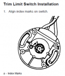
You need to remove the (limit) switch and find the index marks, and align them. This should be the (roughly) full DOWN position. Then start your adjustment procedure.

image_308351.png
 

achris

More fish than mountain goat
Joined
May 19, 2004
Messages
27,468
Ok, remove the switch and hook up a multimeter (Resistance scale, or continuity buzzer). Turn the switch and look/listen and see that it's actually working properly. Then align the index marks when there is continuity (0 ohms)....

Chris........
 

rickasbury

Master Chief Petty Officer
Joined
Jul 13, 2011
Messages
800
Ok, so you have to talk to me like I'm 3.... So I pull the connection apart in the bielge...one of the switches is in the wiring harness going to the pump, the other one connects at the transom and assume that is the one for the limit or the other way around? I have not looked hard to find the wiring diagram for the trim circuit...so when pulled apart and set the meter on conntinuty and have someone slowly spin the wheel on the switch and at a point will lose continutyc, that's what I'm looking for?
 

achris

More fish than mountain goat
Joined
May 19, 2004
Messages
27,468
Yes (turning clockwise). Here's a wiring diagram for you.

fetch
 

rickasbury

Master Chief Petty Officer
Joined
Jul 13, 2011
Messages
800
Thanks achris I'm starting to understand this system way better.....So, if I have the OD trimmed all the way down, the mark lined up on the limit switch and install it all the way left or counter clockwise and I hit the tilt up it should stop at some point and it is not. If it did, I should then be able to loosen the screws and turn it slightly to get to the right dimension and that is not happening. When I pull the motor, I also pulled the pump and the bracket it is on where it mounted on the floor was corroded away so it was flopping around in there....so I fashioned an L piece of aluminum to it so I could re mount it- I don't recall undoing any wires but maybe I did...I have the same diagram as above....I can't tell 100% where exactly on the solenoid they go to - assuming I did not take any wires off and everything there is hooked up, what is next to check? I will do the continuity test you outlined so at lease I would know that the sender is working properly...then on to what? The pump runs fine up and down so no issue there.What else would be wrong down there? I really hope I can wrap this up tomorrow! Any idea for a better diagram of the solenoid that shows for sure what wires go where?? I'm looking on line now....are the solenoids the same for the up and down? Just flipped around? I'm trying to see from pictures how many terminal posts are on them so I can make sense of the above diagram...
 
Last edited:
Top