Mercruiser 3.0 engine ignition wiring issues

Patboat

Cadet
Joined
Jul 22, 2019
Messages
13
Hi Guys,

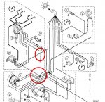
I have recently purchased an EST ignition kit as a replacement for my mercruiser 3.0 of 1989 that had an original DDIS system that no longer produced sparks. As per the recommendations of the seller, the only thing I have to do, is to connect the red wire from the coil to a + supply and the white to -. He also added, as long as it is connected to a switched power wire, it will be fine. I did it, but I couldn't get any sparks to plugs. If I'm having a look to the wiring diagram supplied with the kit (similar to the one in the mercruiser workshop manual), we can clearly realize that the Red wire (from the coil) should be spliced to the purple wire and the white to the grey wire (please see wiring diagram on attachment) I'm getting a bit puzzled coz if I do so I don't get any sparks :-(.
The only wiring that allows me getting a spark, is connecting the red wire to the + from the engine meter (as it's a switched power wire) and leaving the white from coil to the grey. That's way the engine start's up!
Does anyone have a clue why the purple wire (that goes to the alternator) doesn't supply any power? Alternatively, can anyone provide me a better way to wire the ignition properly as leaving it connected to the engine meter sounds like a botched job.
Many thanks,
Pat
 

Attachments

  • photo317244.jpg
    photo317244.jpg
    89 KB · Views: 1
  • photo317244.jpg
    photo317244.jpg
    89 KB · Views: 1
  • photo317244.jpg
    photo317244.jpg
    89 KB · Views: 1

alldodge

Moderator
Staff member
Joined
Mar 8, 2009
Messages
43,326
The DDIS shift interrupter wire (white/Green) went to the switch and then to ground. To make the motor stumble to shift, it would ground the connection. The EST makes the same connect to the switch, but the other sides goes to 12V switched power (Purple)

The EST needs the purple wire going to the Red to the distributor and to the shift switch. To get it running, just leave the White/Green disconnected for now

The white does not go to Negative

Does anyone have a clue why the purple wire (that goes to the alternator) doesn't supply any power?

It should, but it doesn't come from the ALT, the purple wire supplies it to the ALT, check your harness
 

Patboat

Cadet
Joined
Jul 22, 2019
Messages
13
Thank you for the quick replies! Sorry for my lack of knowledge but what do you mean by shift interrupter wire? Is it about the small switch located on the top of the rocker cover? Also thanks for the DDIS wiring diagram posted above. It represents the wiring I had previously, but nothing match my new EST ignition system I'm afraid, as I've had to chuck out all the old DDIS units (e.g. distributor, ECU, coil) :-(. Basically, I have 2 wires only from the new coil that I'm struggling to connect, coz I'm not really sure where they go. According to the instructions provided with the kit, I'm meant to connect the red to purple and white to grey (see pic). but it still doesn't work. What would be the most suitable wire to connect them to?
 

Attachments

  • photo317481.jpg
    photo317481.jpg
    785.6 KB · Views: 0

alldodge

Moderator
Staff member
Joined
Mar 8, 2009
Messages
43,326
Using the connector from the old DDIS unit, attach the Red to the purple, and White to the White/Green.

Slide1.JPG

Then disconnect the Black wire from the **** interrupter switch and attach a new wire to it going to Purple

Slide2.JPG
 

Patboat

Cadet
Joined
Jul 22, 2019
Messages
13
Thank you for very clear explanation. Thanks to you, I put back my engine in a good working order and it goes like a dream!

However, there is a small thing that bother me, you said to disconnect the black wire from the switch then connect the purple wire, but the purple wire provides the battery voltage (12v), so, don't you find strange to connect it to the ground, as the small screw that hold eye terminal is screwed directly into the rocket cover body? See picture below:
 

Attachments

  • photo319275.jpg
    photo319275.jpg
    2 MB · Views: 0
  • photo319276.jpg
    photo319276.jpg
    1.9 MB · Views: 0

Bondo

Moderator
Staff member
Joined
Apr 17, 2002
Messages
71,309
However, there is a small thing that bother me, you said to disconnect the black wire from the switch then connect the purple wire, but the purple wire provides the battery voltage (12v), so, don't you find strange to connect it to the ground, as the small screw that hold eye terminal is screwed directly into the rocket cover body? See picture below:

Ayuh,...... Hook the purple wire to the black wire, but not on the ground terminal screw,.....
 

Patboat

Cadet
Joined
Jul 22, 2019
Messages
13
Ayuh,...... Hook the purple wire to the black wire, but not on the ground terminal screw,.....

Now I can understand why a fuse under the dashboard kept blowing :). Fortunately it's sorted.

I came across this video on youtube: https://www.youtube.com/watch?v=-swDhVcEdh0
the guy state to connect the black wire from the right hand side connector on EST distributor, near the white jump wire, to the switch. May I have your take on that? Thanks. Pat
 

alldodge

Moderator
Staff member
Joined
Mar 8, 2009
Messages
43,326
He is doing it correctly, but has the long wire to where it will connect straight to 12V, and is NOT using the wiring on the motor because it was disconnected by removing the plug on the right connection of the distributor

In post 5
Your converting from DDIS to EST. DDIS uses a "ground" to interrupt the firing of the distributor and "does not" use base timing mode to set timing

EST uses 12V to interrupt the firing of the distributor and "does" require 12V to set base timing.

In post above the "Black" wire is removed from the interrupter connect "and is no longer used".

You need to add a new wire wich has 12V on it when the key is ON. The best place is the purple wire

To place in base timing, attach the jumper between the the 2 white wires which will connect them together. Then connect a jumper at the terminal block which applies 12V to the distributor
 

Patboat

Cadet
Joined
Jul 22, 2019
Messages
13
He is doing it correctly, but has the long wire to where it will connect straight to 12V, and is NOT using the wiring on the motor because it was disconnected by removing the plug on the right connection of the distributor
)

Yes I agree, but if you look at the end of the video (from 1.20 min), he quickly unplug the current connector with jump wire, then he plugs another connector, already prepared in advance with one black wire only, which appears to go to a wire. I can't see properly where it goes as the quality of the video is blurred. What do you think about that? And once again All Dodge, thanks a lot for your time.
 

alldodge

Moderator
Staff member
Joined
Mar 8, 2009
Messages
43,326
)

Yes I agree, but if you look at the end of the video (from 1.20 min), he quickly unplug the current connector with jump wire, then he plugs another connector, already prepared in advance with one black wire only, which appears to go to a wire. I can't see properly where it goes as the quality of the video is blurred. What do you think about that? And once again All Dodge, thanks a lot for your time.

The wire that went to the shift interrupter was removed from the distributor. That single "Black" wire is connected is connected to the interrupter switch.

The right side dizzy connector can be a single wire that only goes to shift interrupter, OR can be a connector which has 2 additional short "not connected" white wires.

He did not have the right side connector with 3 wires, and only had the one. So he used an additional connector which had the white wires already connected together, and an additional wire which supplied 12V (connected to starter post) to place the motor in base timing.

It would be better if the vid discussed these discrepancies but it did not.
 

Patboat

Cadet
Joined
Jul 22, 2019
Messages
13
To place in base timing, attach the jumper between the the 2 white wires which will connect them together. Then connect a jumper at the terminal block which applies 12V to the distributor

Ok its duly noted that I need to Jump the 2 white wires and to connect the black wire to 12V to trigger the base timing mode.

Once the timing has been done, I was wondering how to do to return to the automatic timing mode? Do I have to disconnect the jump with white wire and the black wire from his power supply or just unplugging the whole plug?

I also have some queries about the timing advance degrees as the instructions from the distributor state to set the timing at 0° at 500rpm, then I read into the mercruiser instructions which is from a newer version of my engine to set the timing at 1° Before TDC. I'm getting a bit confused, so does anyone know what is the correct timing for my engine which is from 1989 and has the following serial number, is it may helps: 0C678976

Many thanks
 

alldodge

Moderator
Staff member
Joined
Mar 8, 2009
Messages
43,326
Once the timing has been done, I was wondering how to do to return to the automatic timing mode? Do I have to disconnect the jump with white wire and the black wire from his power supply or just unplugging the whole plug?

Just disconnect the jumper between the 2 white wires

Then disconnect the jumper connecting both sides (terminals) of the shift interrupter

I would set timing at 1 BTDC
 

Patboat

Cadet
Joined
Jul 22, 2019
Messages
13
Ok noted! thanks again.
For the tiiming, yeah 1 BTDC is exactly what I did :)

Sorry to be a burden, but what am I meant to do with the black wire from the dizzy connector? Shall I leave it disconnnected and with the bottom end taped?
 

alldodge

Moderator
Staff member
Joined
Mar 8, 2009
Messages
43,326
Its OK, some folks just have more trouble then others understanding electrical issues.

But no you do not want to leave it tapped and not connected. The wire coming from the dizzy must be connected to a switch, which will supply 12V when the swicth is activated.

Take your time but go back thru the posts and re-read what is being said. They reinforce the same questions asked with the same answers

If it still is unclear, its ok, just ask again and I'll try another way

I will be out tomorrow because I'm picking up a tractor and bat wing mower
 
Top