MC-1 165’s seastar install hangup

ttownthomas

Petty Officer 1st Class
Joined
Jun 7, 2019
Messages
204
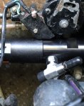
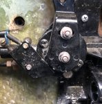
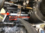
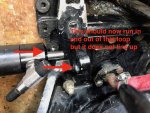
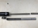
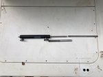
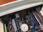
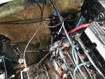
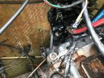
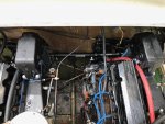
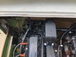
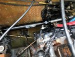
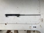
I’m replacing my cable driven mechanical steering with sea star hydraulic steering. The ram is supposed to thre hread onto the support tube to install it but when I try to fit it up the reverse lock solenoid assembly is in the Way. As a result I can’t line it up straight enough to install it.
 

Attachments

  • photo319869.jpg
    photo319869.jpg
    1.7 MB · Views: 1

Bondo

Moderator
Staff member
Joined
Apr 17, 2002
Messages
71,309
but when I try to fit it up the reverse lock solenoid assembly is in the Way.

Ayuh,..... Yer gonna have to move it to get clearance, if you want hyd. steering,.....
 

ttownthomas

Petty Officer 1st Class
Joined
Jun 7, 2019
Messages
204
been thinking about upgrading to alpha 1 pumps and getting rid of the reverse lock anyway. Is that a viable solution?
 

ttownthomas

Petty Officer 1st Class
Joined
Jun 7, 2019
Messages
204
Why is there a reverse lock out? Does it have something to do with the plastic hydraulic lines on the reverse side of the system? Meaning they can get into an over-pressure situation if you're running in reverse and the circuit opens at the same time blowing out the lines?

Also why does upgrading to the alpha one hydraulics solve that problem? Does it simply have more robust lines? When I remove the system and replace it with the alpha one do I just route the lines from the pump right to the drives bypassing all the lock out stuff? Or can I also remove the solenoid itself too?

I know that is alot of queations. Sorry
 

ttownthomas

Petty Officer 1st Class
Joined
Jun 7, 2019
Messages
204
How do I remove the solenoids. It looks like the forward and reverse levers are attached to it
 

Attachments

  • photo319913.jpg
    photo319913.jpg
    1.7 MB · Views: 0

ttownthomas

Petty Officer 1st Class
Joined
Jun 7, 2019
Messages
204
MC-1 inner transom assemblies not lined up preventing hydraulic steering install

I'm installing seastar hydraulic steering on my 1972 Bertram. It has GM inline 6's and MC-1 drives. The inner transom assembly has loops on it that have a thread-in tube that used to hold the cable steering ends. That threaded tube threads into the seastar ram and the tube is supposed to attach to one assembly and then a tie bar is used to mate the 2 tiller arms together.

Problem is that the loops on the 2 inner transom assemblies are not inline anymore (or mabee they never were) and I cannot mount the ram in a way that its motion does not get impeded by other equipment. I flipped the ram backwards in these pictures to illustrate the problem.

Seems like I can either:

remove the bolts holding in the transom assemblies and shim them to line up correctly

or

Ditch the loop mounted ram and install one that bolts directly to the transom.
 

Attachments

  • photo320383.jpg
    photo320383.jpg
    394.4 KB · Views: 0
  • photo320384.jpg
    photo320384.jpg
    385.2 KB · Views: 0

Bt Doctur

Supreme Mariner
Joined
Aug 29, 2004
Messages
19,453
Didnt see that type on the seastar site mount the cylinder ans link to the stbd arm and tie bar to the port one
 

ttownthomas

Petty Officer 1st Class
Joined
Jun 7, 2019
Messages
204
There’s not enough room on the starboard side of the starboard Drive. It Has to go on the starboard side of the port Drive
 

Bondo

Moderator
Staff member
Joined
Apr 17, 2002
Messages
71,309
Donno,..... I'm still tryin' to figure out what's in yer pictures,....

Is the cable originally mounted to the transom plate, outboard motor style, like a false tilt-tube attachment,..???
That's older than I see,....

Does the rod of the ram somehow run through the ring, or is that "T" lookin' thing, is the mount, to go into the ring on the transom plate,..??

A picture further back might help,....
another with all the bits ya got to work with would help too,....
 

GA_Boater

Honorary Moderator Emeritus
Joined
May 24, 2011
Messages
49,038
ttown - Combined both threads about your hydraulic steering upgrade. Less confusion with one thread.

But you need a couple more pics further back so we can see the big picture. :smile:
 

ttownthomas

Petty Officer 1st Class
Joined
Jun 7, 2019
Messages
204
[No message]
 

Attachments

  • photo320412.jpg
    photo320412.jpg
    309.8 KB · Views: 0
  • photo320413.jpg
    photo320413.jpg
    248.5 KB · Views: 0
  • photo320414.jpg
    photo320414.jpg
    356.2 KB · Views: 0
  • photo320415.jpg
    photo320415.jpg
    419.7 KB · Views: 0
  • photo320416.jpg
    photo320416.jpg
    401.5 KB · Views: 0
  • photo320417.jpg
    photo320417.jpg
    369.7 KB · Views: 0
  • photo320418.jpg
    photo320418.jpg
    324.8 KB · Views: 0
  • photo320419.jpg
    photo320419.jpg
    454.3 KB · Views: 0
  • photo320420.jpg
    photo320420.jpg
    268.5 KB · Views: 0
  • photo320421.png
    photo320421.png
    22.6 KB · Views: 0

Bondo

Moderator
Staff member
Joined
Apr 17, 2002
Messages
71,309
Ayuh,...... Is the rod(silver) stickin' outa the starboard side of the ram(black), extend as the other end retracts,..??
 

ttownthomas

Petty Officer 1st Class
Joined
Jun 7, 2019
Messages
204
Ayuh,...... Is the rod(silver) stickin' outa the starboard side of the ram(black), extend as the other end retracts,..??

Yep. and since the mounting loops don't line up perfectly the silver rod will get hung up when it extends
 
Top