Big twin flywheel compatibility

dh_user

Cadet
Joined
Mar 30, 2017
Messages
21
Does anyone know if flywheel 580335 (1959 Evinrude 35hp) is compatible with flywheel 580334 (1961 evinrude 40hp)? Background and details below.

I'm restoring a 1961 evinrude 40hp (35524). The old flywheel (presumably it was original, pn 580334) had a bad taper, bad keyway, etc. (broken crankshaft looked like a big explosion). I found a flywheel from a 1959 35hp (I think pn 580335), and it started after considerable effort, but it runs terrible.
. Confirmed fuel (bulb squeeze fills high speed circuit, and when running I can see the jet delivering fuel with the carb screen off at lower throttle)
. Compression is 105 top, 110 bottom (I honed cylinders, etc.)
. Confirmed decent spark across 1/4" gap using the basic gap tool
. Points gap is. 020 when the inspection port is right above the points (and cam is at high point for that cylinder)
. I don't have a timing tool for this engine, and the flywheel has absolutely no markings, but the points open and go to infinite ohms at two points I marked with a sharpie, pretty much exactly 180 degrees apart on the flywheel
I can't get this thing to run more than 45 to 60 seconds no matter what I do. Could it be the flywheel is that different? looks so similar.
Magnet size and shape looks just like the old one that came on the engine, but I'm just not sure.
 

racerone

Supreme Mariner
Joined
Dec 28, 2013
Messages
38,897
The flywheel does have 2 timing marks that can be used to set the points.-----The factory timing fixture is nothing but a " dummy flywheel ".-----So with some care you can use your flywheel !!----If it runs for 45 to 60 seconds you might want to look at fuel issues.
 

dh_user

Cadet
Joined
Mar 30, 2017
Messages
21
Thanks racerone! I've marked on the flywheel where the points open up, but even with a bright light, feeling for scribe marks with my fingers, etc, I can't find existing markings to see whether my marks are correct or not. I considered ordering the timing tool, since I don't have any trusted reference, so will probably do that.

Also considered your point about it possibly being a fuel issue. I rebuilt both the pump/sediment bowl and the carb and tested to make sure theres no leakage the wrong way across the pulse valve. Bulb squeeze fills carb bowl, and when I turn over the engine with choke set to auto, I do see the fuel /oil mixture begin to drip out of the front of the carb. Will test the fuel pump vacuum when turning the engine over to make sure there's enough suction. Any other suggestions to eliminate fuel as a possibility?
 

racerone

Supreme Mariner
Joined
Dec 28, 2013
Messages
38,897
Timing marks ( 2 of them ) have been on every flywheel that uses those coils / points / condensers from about 1950 to late 1980's.------Just a matter of finding them on your flywheel.----Yes they are on your flywheel.-----They can be used to set the points using an ohmmeter.-----On search on google for videos that demonstrate this simple technique.
 

dh_user

Cadet
Joined
Mar 30, 2017
Messages
21
I trust you, and it's not the technique that's hanging me up, but I just can't see or find the marks. Will keep looking .
 

racerone

Supreme Mariner
Joined
Dec 28, 2013
Messages
38,897
Remove sparkplugs.-----Pull throttle to slowest idle.----Put #1 at top dead center.-----Look above / near the 2 vertical marks on the magplate.-----You should see a mark on the flywheel there, hopefully between the 2 lines.----#2 should be at 180 degrees.
 

jimmbo

Supreme Mariner
Joined
May 24, 2004
Messages
13,961
. Points gap is. 020 when the inspection port is right above the points (and cam is at high point for that cylinder)
.


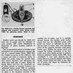
The 1958 35 hp Owners Manual said to adjust the points to 0.020" thru the hole in the flywheel. Granted using the Timing Fixture and the timing Marks did set the exact spot when the points opened
Click image for larger version  Name:	img117ab.jpg Views:	1 Size:	201.0 KB ID:	10810419
 

dh_user

Cadet
Joined
Mar 30, 2017
Messages
21
Thanks jimmbo! That picture helps too. That's the way they're set currently... 0.020" gap when that hole / inspection port in the flywheel is directly above the point.

When I get back to it this weekend, I'm going to look a little harder on the flywheel for those markings, to see if they are in similar locations to where I marked the "points open" spots. If they are, then it seems like I've confirmed everything I can on the ignition (. 020 gap at high point on the cam; ohm meter confirms points begin to open when at TDC and the flywheel mark passes between armature plate marks with plate set at slowest idle). I'll confirm spark using a gap tester one more time, and then I'll focus on the fuel system as racerone recommended .
 

jimmbo

Supreme Mariner
Joined
May 24, 2004
Messages
13,961
I was referring to a Timing Fixture that is installed on the End of the crank shaft after the Flywheel is removed
img118a.jpg
 

Willyclay

Captain
Joined
Sep 8, 2006
Messages
3,268
When members jimmbo and racerone post in a thread, I pay attention because they are pro's and I hope to learn something new. Factory and non-factory manuals note the flywheel installation on 1960 & later 40HP models as requiring extreme caution to assure seating on the crankshaft taper due to the smaller key slot to accommodate "the smaller key, p/n 307480". This issue may be the source of the damage you found. Good luck with that great old motor!
 

Willyclay

Captain
Joined
Sep 8, 2006
Messages
3,268
Also found Service Bulletin No. 833 dated 03/27/61 describing replacement connecting rods that are stronger and use a new type 12-point Cap screw.
 

dh_user

Cadet
Joined
Mar 30, 2017
Messages
21
Thanks Willyclay. Agree with you on racerone and jimmbo; their advice is always quick and right on target. Also appreciate your help with the additional service notes.
 

dh_user

Cadet
Joined
Mar 30, 2017
Messages
21
A couple of updates here. I spent the morning reading some other threads on timing and carbs (and re-reading the service manuals). Really appreciate all your help and advice.
1. Spark: confirmed spark with plug in boot and alligator leads from side electrode to ground.
2. Points: I did see that the #2 point alignment was really sloppy (the rocker side was nice and even, but the common side was too high and also just angled wrong... I could see air space between the "closed" points and the armature plate). I took some 320 sandpaper to the common side but never got happy with it, and when adjusting the height I broke the plastic insulating layer. These are omc parts. I went back and compared that common side point to some old omc (and unused sierra) parts, and it's just no good. Swapped out, replaced, re-gapped, re-timed, and slid in a card dipped in acetone.
3. Timing: I got the timing tool from Richard at classicomctools, to confirm my points were opening at the right time. All was good there, and I used that reference to mark my flywheel (I'm obviously just not seeing /feeling the factory markings, but it doesn't matter anymore because I have nice new sharpie lines now).
 

dh_user

Cadet
Joined
Mar 30, 2017
Messages
21
Also, would like to get the group's advice on whether the 2 intake gaskets (manifold to reed plate, reed plate to block) should be sealed or not. If yes, would you use BMP Sealer / Permatex 3, or something else?

Potential vaccum issue: this is the first time I've opened a crank case, so I re-read some service manuals and went back to look at my photos from the process (mostly checking hardening vs non-hardening sealers, thread sealers, etc). Everything in the crank case looks right, seals are oriented correctly. Torque values are all correct. All that said, I didn't use any sealer on the intake gaskets (intake manifold to reed plate, or reed plate to block). That (and the head gasket) is the only place I didn't use gasket sealer. Every gasket on the engine is new. At the time, I read some threads, and the consistent advice was not to seal new gaskets on the intake side, but the condensed service manuals seem to indicate everything should be sealed: "the crank case and intake manifold must be completely sealed against both vacuum and pressure." What do you guys think on this one?
 

F_R

Supreme Mariner
Joined
Jul 7, 2006
Messages
28,226
NO sealer on the intake gaskets. The gaskets are sufficient to satisfy the "completely sealed" requirement.
 

jimmbo

Supreme Mariner
Joined
May 24, 2004
Messages
13,961
A little tidbit about adjusting points. Using a feeler gauge is really only accurate on Brand New points, as the surfaces are nice and smooth. Used/filed/sanded points no longer smooth and the roughness results in a gap slightly greater than the Feeler gauge, which can affect Spark Timing. Flat Gauges result in a greater error than the round type. Used/filed/sanded points are best set using the Timing Fixtures and/or Marks, as that is where the points are expected to break Continuity
 

dh_user

Cadet
Joined
Mar 30, 2017
Messages
21
Thanks F_R.
Thanks jimmbo. I got the timing tool from Richard at classicomctools, to confirm my points were opening at the right time (ohmmeter goes to infinite when timing tool mark passes the magneto plate gap). All was good there, and I used that reference to mark my flywheel. New omc points as indicated. In the end, the ".020 when the inspection port was above the points adjustment screw" was a pretty close match to the continuity test method with the flywheel markings / timing tool. I did adjust one of the points slightly; the other was the same using either method.

Appreciate the feedback on the intake gaskets. I'll go back and confirm sync, link, and fuel.
 

oldboat1

Fleet Admiral
Joined
Apr 3, 2002
Messages
9,612
You need a working t.stat for the auto choke to work properly. Initially, it's probably a good idea to run on the manual choke setting. There should not be fuel running out of the carb throat, and would guess over-choking or misadjusted float. If you open up the carb, do a full cleaning and put in a kit. Before doing any carb work, though, better part of wisdom is to reset and adjust the low speed needle. (about 1 turn open for the initial setting. Start and warm up, then adjust for leanest setting where engine runs smoothly.)
 

jimmbo

Supreme Mariner
Joined
May 24, 2004
Messages
13,961
A 61 would also have a Adjustable High Speed Needle. Initial setting is One turn from lightly seated. Ajust this one before the Idle Mix, and then recheck it after the idle is adjusted
 
Top