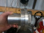
Alignment witness marks

chartersj

Petty Officer 1st Class
Joined
May 14, 2013
Messages
281
I changed my old style motor mounts to the new style knurled type and having trouble with alignment. It's close, but in the pictures you can see I have heavier marks on the top of the tool and lighter on the bottom. I have set the bearing multiple times and used the provided SS washers. It wasn't close without them. The tool slides in and out with some pressure, cannot do it with two fingers. I need to bring the front of the motor down more or does it look close enough?
 

Attachments

  • IMG_20200412_100414.jpg
    IMG_20200412_100414.jpg
    1.3 MB · Views: 3
  • IMG_20200412_100442.jpg
    IMG_20200412_100442.jpg
    1.3 MB · Views: 3

alldodge

Moderator
Staff member
Joined
Mar 8, 2009
Messages
43,321
Does anything change when the motor is rotated 90 degrees?
Are you smacking the alignment tool with hand all around, once inserted after each adjustment to center the gimbal bearing?
 

chartersj

Petty Officer 1st Class
Joined
May 14, 2013
Messages
281
Does anything change when the motor is rotated 90 degrees?
Are you smacking the alignment tool with hand all around, once inserted after each adjustment to center the gimbal bearing?

Yep I did rotate 90 degrees and kept setting the gimbal bearing. It seems the rear isn't exact to me. If I adjusted the front up or down from here the tool would start to wedge itself in the splines and wouldn't bottom out would it not?
 

alldodge

Moderator
Staff member
Joined
Mar 8, 2009
Messages
43,321
It could be in a slight twist (one side higher then the other) or the mounts not fully seated. Otherwise need a tool to determine which way it needs to go

Alignment 91-863372.jpg
 

Bt Doctur

Supreme Mariner
Joined
Aug 29, 2004
Messages
19,453
Can you locate a used inputshaft and have the area where the gimbal bearing rides machined 1/8 unsersized and machine off the yoke end. center drill and tap for a removal bolt . insert into coupler and using a 1/8 inch rod of some type, (welding/brazing,etc) take a measurement os eyeball witch way it`s off.
 

chartersj

Petty Officer 1st Class
Joined
May 14, 2013
Messages
281
It could be in a slight twist (one side higher then the other) or the mounts not fully seated. Otherwise need a tool to determine which way it needs to go


now that you say that there is no pull eye on the center on the front on the motor (496) it is on the port side. So I was pulling up off the side some when trying to align. But it is the factory eye.
 

chartersj

Petty Officer 1st Class
Joined
May 14, 2013
Messages
281
Can you locate a used inputshaft and have the area where the gimbal bearing rides machined 1/8 unsersized and machine off the yoke end. center drill and tap for a removal bolt . insert into coupler and using a 1/8 inch rod of some type, (welding/brazing,etc) take a measurement os eyeball witch way it`s off.

I see what your saying and I do know I can get my hands on one. That's also a good idea
 

Scott06

Admiral
Joined
Apr 20, 2014
Messages
7,178
I changed my old style motor mounts to the new style knurled type and having trouble with alignment. It's close, but in the pictures you can see I have heavier marks on the top of the tool and lighter on the bottom. I have set the bearing multiple times and used the provided SS washers. It wasn't close without them. The tool slides in and out with some pressure, cannot do it with two fingers. I need to bring the front of the motor down more or does it look close enough?
I think you are close enough. Also consider if you do a bunch of alignment checks you end up with a bunch of grease in the coupler which can make it tough to get the tool in and out (no jokes...)
 

chartersj

Petty Officer 1st Class
Joined
May 14, 2013
Messages
281
Thought I would give anyone interested an update. After looking everything over again I noticed the ears on the inner transom plate where the rear motor mounts sit have wore down a very small amount so the rear was down a little lower then it should be. I made some small shims to make up the difference and now the alignment is spot on. Easily slides in and out with two fingers and have even witness marks all around the tool.
 

tank1949

Lieutenant Commander
Joined
Apr 4, 2013
Messages
1,911
I changed my old style motor mounts to the new style knurled type and having trouble with alignment. It's close, but in the pictures you can see I have heavier marks on the top of the tool and lighter on the bottom. I have set the bearing multiple times and used the provided SS washers. It wasn't close without them. The tool slides in and out with some pressure, cannot do it with two fingers. I need to bring the front of the motor down more or does it look close enough?

1996? Perhaps stringers or transom rot is causing issues like flexing under weight. Why did you replace mounts in the first place? I have never used ss steel washers with an alignment tool.
 

chartersj

Petty Officer 1st Class
Joined
May 14, 2013
Messages
281
1996? Perhaps stringers or transom rot is causing issues like flexing under weight. Why did you replace mounts in the first place? I have never used ss steel washers with an alignment tool.

The previous owner didn't have the 1/2" spacer under the bolt and washer and it forced the back of the motor down and over time collapsed the motor mounts. The new style knurled mounts have ss washers that replace the spring washers.

I checked the transom while the motor was out and it's good, and this boat doesn't have conventional stringers it has fiberglass boxes molded to the hull
 

tank1949

Lieutenant Commander
Joined
Apr 4, 2013
Messages
1,911
The previous owner didn't have the 1/2" spacer under the bolt and washer and it forced the back of the motor down and over time collapsed the motor mounts. The new style knurled mounts have ss washers that replace the spring washers.

I checked the transom while the motor was out and it's good, and this boat doesn't have conventional stringers it has fiberglass boxes molded to the hull

We had a hell of a time setting v8 on top of traditional spring/leather washer mounts. We kept bumping them off underneath v8's bellhousing while trying to install engine, but we couldn't see that they had become dislodged. Getting spline tool aligned was impossible. My engine "hole" is very small and difficult for a normal sized person to fit into it and watch to be sure spring/washer wasn't dislodged. Only by chance did we see "bumped" washers in the bottom of bilge. We finally used a mirror to verify fitting, after using contact cement to hold washer/spring in place. In addition, old coupler (used on rotten transom) had been slightly warped due to fatigue from rotten transom. I feel your pain!
 

chartersj

Petty Officer 1st Class
Joined
May 14, 2013
Messages
281
We had a hell of a time setting v8 on top of traditional spring/leather washer mounts. We kept bumping them off underneath v8's bellhousing while trying to install engine, but we couldn't see that they had become dislodged. Getting spline tool aligned was impossible. My engine "hole" is very small and difficult for a normal sized person to fit into it and watch to be sure spring/washer wasn't dislodged. Only by chance did we see "bumped" washers in the bottom of bilge. We finally used a mirror to verify fitting, after using contact cement to hold washer/spring in place. In addition, old coupler (used on rotten transom) had been slightly warped due to fatigue from rotten transom. I feel your pain!

I could see how it would be tricky with limited space. Luckily I have lots of room on either side of the engine. I was a little concerned about my coupler as well but alignment stayed the same after turning motor over a few times and re-checking. Definitely a good feeling when you get spot on. I will check again this fall and see if I will have to change the inner transom plate or not.
 

tank1949

Lieutenant Commander
Joined
Apr 4, 2013
Messages
1,911
I could see how it would be tricky with limited space. Luckily I have lots of room on either side of the engine. I was a little concerned about my coupler as well but alignment stayed the same after turning motor over a few times and re-checking. Definitely a good feeling when you get spot on. I will check again this fall and see if I will have to change the inner transom plate or not.

Perhaps and pray your transom and/or stringers are synthetic. Then, no worries! If not and your boat is a 96, expect a transom rebuild. Unscrew transducer or trim tab screws. If water or crud comes out, expect a rebuild. I've been there! Good luck!
 

pyrotek

Petty Officer 2nd Class
Joined
Nov 19, 2011
Messages
183
You cannot really adjust for left-right alignment. You place the pins/bolts in the rear motor mounts and you then cannot adjust left-right. The only way to get left/right alignment is to compress the rubber in the rear mounts or the slop between the bolt and the rear motor mount hole, of which both I don't think is significant.

You can also rotate the engine along the axis of the driveshaft by only turning one side. I've read the best way to do this is to lift the engine up slightly by the center hook which you don't have. I also was not able to do this, so I measured the height of the rear motor mounts sticking up. Kind of hard to explain, but the 1/2" spacer, washer and bolt head ride on the inside of the rubber motor mount. The outside is fixed to the motor bell housing which sits in a lip and cannot go up. So if one side of the spacer is sticking up high, it means there is more load on that side pushing the inside rubber, and bolt head up. I adjusted front left/right so this gap was even, theoritically having even load on the rear engine mounts. I figured this out when one rear mount was originally not even touching (after rebuild) and the engine was basically sitting on 3 points. From there, I went up/down together to get alignment correct. If witness marks are on top, raise the front of the engine. If witness marks on the bottom, lower the front of the engine.

They also sell spacers in the rare case that the alignment does not line up. Seems like it may be older models that need this, but I'm not sure on the details.
 

tank1949

Lieutenant Commander
Joined
Apr 4, 2013
Messages
1,911
Thought I would give anyone interested an update. After looking everything over again I noticed the ears on the inner transom plate where the rear motor mounts sit have wore down a very small amount so the rear was down a little lower then it should be. I made some small shims to make up the difference and now the alignment is spot on. Easily slides in and out with two fingers and have even witness marks all around the tool.

So how did you measure distance needed for the additional shims and thickness of shims? I suspect all older inner MC transom plates are worn. I had to replace both of mine. After all they are aluminum, and they have hundreds of pounds of steel resting and rubbing on them over time? What did you use as a datum point for determining that you needed shims or was it just SWAG? Good guess if SWAG!!!!!
 

chartersj

Petty Officer 1st Class
Joined
May 14, 2013
Messages
281
So how did you measure distance needed for the additional shims and thickness of shims? I suspect all older inner MC transom plates are worn. I had to replace both of mine. After all they are aluminum, and they have hundreds of pounds of steel resting and rubbing on them over time? What did you use as a datum point for determining that you needed shims or was it just SWAG? Good guess if SWAG!!!!!

I made 3 different sizes and put the closest set in which was the thinnest ones. It was not an exact science but it worked lol
 
Top