Lateral engine alignment

AShipShow

Lieutenant Commander
Joined
Jul 8, 2016
Messages
1,803
Hello all,
I'm trying to align my 1996 mercruiser 5.7L with alpha 1 gen 2 after a full restoration. Everything with the transom was in spec after the rebuild... i seem to be getting heavier spline marks on the starboard side of the alignment tool... my first instinct was to rotate the engine... I spun it 180 degrees and it's still heavy on the starboard side so I assume bent coupler is ruled out...

My only guess at this point is the front mounts are out of the correct location...

Are there any other possibilities that could cause this?

Last night I loosened the rear mounts and removed the lag screws from the front mounts and lifted it by the thermostat housing lift point and the port side front mount was a little off once the motor centered itself and the starboard side mount was pretty close... doesnt quite seem enough to be the issue... hoping it is but want to make sure I'm not missing something before I remove the engine, fill, and redrill the front mounts...

Thanks
 

Rick Stephens

Admiral
Joined
Aug 13, 2013
Messages
6,118
If you are hanging from the front alignment loop then the front motor mounts don't have anything to do with getting good alignment. Only rear mounts and gimbal bearing matter.
 

achris

More fish than mountain goat
Joined
May 19, 2004
Messages
27,468
If the front mounts aren't biasing the engine in either direction (hanging on the front lifting eye, side mount screws removed), all other things being correct (right torque on the rear mount screws), then the only thing that can create a sideways misalignment is the transom being uneven. It's thicker on one side.

Chris.......
 

Rick Stephens

Admiral
Joined
Aug 13, 2013
Messages
6,118
If the front mounts aren't biasing the engine in either direction (hanging on the front lifting eye, side mount screws removed), all other things being correct (right torque on the rear mount screws), then the only thing that can create a sideways misalignment is the transom being uneven. It's thicker on one side.

Chris.......

Chris,

I don't think even that would do it. The gimbal bearing can be aimed easily even way out of true on the transom thicknesses. I think the only things that matter when hanging the front is rear motor mounts and coupler. Transom plate and gimbal housing are bolted solid together, even if off a bit on parallel, the gimbal bearing would still sit middle of transom plate.
 

AShipShow

Lieutenant Commander
Joined
Jul 8, 2016
Messages
1,803
I checked the transom after my glass work was done and everything checked out so I'm confident that's not the issue...

The other thing that's frustrating is, it seems like everytime I check alignment I get a little different results... I might check the spline marks, resmooth the grease, and check again without adjusting and it might look a little different... would that be the gimbal bearing moving around?

Dunno, just feels like it's impossible to know which way to adjust when the marks aren't very clear...
 

achris

More fish than mountain goat
Joined
May 19, 2004
Messages
27,468
I don't think even that would do it. The gimbal bearing can be aimed easily even way out of true on the transom thicknesses....

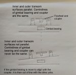
There's a reason why Merc spec the 'parallelism' of the inner and outer surfaces of the transom. It matters, and is the main reason for apparent lateral misalignment... The quick diagram below shows the horizontal references for the couple, gimbal bearing and transom surfaces. I have exaggerated the taper, just for clarity. Any variation in how parallel the 2 surfaces are will have an affect on the lateral alignment.

Chris..........

alignment.jpg
 

Rick Stephens

Admiral
Joined
Aug 13, 2013
Messages
6,118
There's a reason why Merc spec the 'parallelism' of the inner and outer surfaces of the transom. It matters, and is the main reason for apparent lateral misalignment... The quick diagram below shows the horizontal references for the couple, gimbal bearing and transom surfaces. I have exaggerated the taper, just for clarity. Any variation in how parallel the 2 surfaces are will have an affect on the lateral alignment.

Chris..........

I don't believe that not parallel would show up as a misalignment with the alignment tool. Yes, the issue is the constant velocity joint then gets put to the side when the surfaces aren't parallel. But you cannot see or test for that with the alignment bar,. That has to be done previously only by ensuring the transom surfaces are parallel before installing plate and gimbal housing. If the alignment bar is showing heavy marks on one side, the engine is not straight to the rear mounts. There is something out of whack with the rear mounts with the engine hanging from the alignment loop.


I would recommend loosening the rear mount bolts and shifting the motor side to side and then re-torquing the rear mounts. Retest and see if you are straight.

Rick
 

tank1949

Lieutenant Commander
Joined
Apr 4, 2013
Messages
1,911
Hello all,
I'm trying to align my 1996 mercruiser 5.7L with alpha 1 gen 2 after a full restoration. Everything with the transom was in spec after the rebuild... i seem to be getting heavier spline marks on the starboard side of the alignment tool... my first instinct was to rotate the engine... I spun it 180 degrees and it's still heavy on the starboard side so I assume bent coupler is ruled out...

My only guess at this point is the front mounts are out of the correct location...

Are there any other possibilities that could cause this?

Last night I loosened the rear mounts and removed the lag screws from the front mounts and lifted it by the thermostat housing lift point and the port side front mount was a little off once the motor centered itself and the starboard side mount was pretty close... doesnt quite seem enough to be the issue... hoping it is but want to make sure I'm not missing something before I remove the engine, fill, and redrill the front mounts...

Thanks

Rotten transom may have warped coupler. This virus isolation is keeping friends from helping me test this possibility as identified by other Iboat contributors. I order new coupler, just in case mine was wrapped by undo pressure asserted by rotten transom. My rebuilt transom is parallel, but we are on hold at completing the job, just like many other boaters. I feel your pain!!!! If you have dial indicator with a long enough reach (mine didn't have it) you may be able to turn motor over with alignment tool inserted and examine runout. That's a sure bet that coupler is or is not bad and you need to pull transom assembly. Another issue that may cause you headaches is when you locked down forward engine mounts (with lag bolts) was motor under a bind and possibly torqued port or starboard. The rear engine mount holes may have become egg shaped due to rotten transom flexing too. This possibility keeps raising its ugly head in my mind. Good luck!
 

AShipShow

Lieutenant Commander
Joined
Jul 8, 2016
Messages
1,803
Rotten transom may have warped coupler. This virus isolation is keeping friends from helping me test this possibility as identified by other Iboat contributors. I order new coupler, just in case mine was wrapped by undo pressure asserted by rotten transom. My rebuilt transom is parallel, but we are on hold at completing the job, just like many other boaters. I feel your pain!!!! If you have dial indicator with a long enough reach (mine didn't have it) you may be able to turn motor over with alignment tool inserted and examine runout. That's a sure bet that coupler is or is not bad and you need to pull transom assembly. Another issue that may cause you headaches is when you locked down forward engine mounts (with lag bolts) was motor under a bind and possibly torqued port or starboard. The rear engine mount holes may have become egg shaped due to rotten transom flexing too. This possibility keeps raising its ugly head in my mind. Good luck!

I'm reasonably certain that the coupler is not the issue... if the coupler was warped or bent, the spline marks would change as I turn over the motor but they seem to stay consistent. Thats why I'm fairly convinced its a front mount/maaaaaybe rear mount issue.

Rick Stevens
I might have come across a little confusing... I don't know if the spline marks were STILL heavy when hanging from the thermostat loop because it was tough to get the alignment bar in since I don't have much fine control of the height with the chain hoist to get it dialed in...

Is there something I should be looking for with the rear engine mounts that may indicate they are bad?


EDIT: one other thing, i thought the transom had to be parallel within 1/16", but I just saw its 1/8", thats like a mile over an area the size of the transom plate... I'm 100% sure im within that because I'm pretty sure I checked it thinking it was 1/16" at the time...
 
Last edited:

Rick Stephens

Admiral
Joined
Aug 13, 2013
Messages
6,118
I'm reasonably certain that the coupler is not the issue... if the coupler was warped or bent, the spline marks would change as I turn over the motor but they seem to stay consistent. Thats why I'm fairly convinced its a front mount/maaaaaybe rear mount issue.

Rick Stevens
I might have come across a little confusing... I don't know if the spline marks were STILL heavy when hanging from the thermostat loop because it was tough to get the alignment bar in since I don't have much fine control of the height with the chain hoist to get it dialed in...

Is there something I should be looking for with the rear engine mounts that may indicate they are bad?

First is uneven height of the motor side (bellhousing) on the transom plate ears.

I think all you can do with your motor hanging is make the front motor mounts identical and leave the lag screws out. As long as they sit down evenly you have done all you can with the hoist.

When you loosen rear bolts and pull/push do you get any side to side movement at the front of the motor, with the front motor mounts not screwed down?

Rick
 

AShipShow

Lieutenant Commander
Joined
Jul 8, 2016
Messages
1,803
When you loosen rear bolts and pull/push do you get any side to side movement at the front of the motor, with the front motor mounts not screwed down?

Rick

I don't think so, I will have to confirm that though.. I assume I will need to remove the rubber couplers from the exhaust to do this check as they will probably prevent the motor from shifting around..
 

harringtondav

Commander
Joined
May 26, 2018
Messages
2,442
Mad Props I had to replace my front mounts due to a frozen adjuster and broken lag screws on each mount. I had my engine out to fix the broken lag stubs. To get things lined back up I set the engine on the mounts, tuned vertical alignment as well as I could, then ginched the engine sideways until I got good side alignment. Then marked the mount locations, lifted engine, and lagged in the mounts. Then a final fine tune on the alignment.

If you consider how much vertical alignment changes with 1/2 an adjuster turn, you can see how much side to side error will affect alignment.

BTW While I had my engine out I replaced my 22 yr old rear mounts and other parts that were rarely accessible.
 

AShipShow

Lieutenant Commander
Joined
Jul 8, 2016
Messages
1,803
I just went out to take some measurements on my alignment tool to make sure its within spec just to rule things out... (it is) and for gits and shiggles I popped it in the boat and it went in super easy lol... Its currently sitting on the front mounts that aren't lagged in, so I think redrilling the front mounts is gonna get me there... I'll follow up when I get my mounts redrilled and recheck the alignment
 

harringtondav

Commander
Joined
May 26, 2018
Messages
2,442
The spline minor diameter pilot on the alignment tool is under size from the coupler spline's minor diameter. SAE spec on the coupler minor dia ispline is 1.005"/1.000". The tool's pilot is 1.001" dia. Possible interference. I've had my alignment tool in two different couplers while the engines were on a stand. There was quite a bit of looseness.

I'm guessing Merc had the coupler spline bored somewhat over spec to allow for part tolerance stack up between the gimbal hsg. transom hsg., and the flywheel cover.

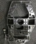
I notice the transom hsg's mounting through holes are vertically slotted. Is there an alignment process when reassembling the gimbal hsg to the transom hsg to ensure correct alignment? Looks like there is potential for these two not lining up. That could put the coupler quite a bit off from design intent.

Merc transom plate.JPG
 

AShipShow

Lieutenant Commander
Joined
Jul 8, 2016
Messages
1,803
The spline minor diameter pilot on the alignment tool is under size from the coupler spline's minor diameter. SAE spec on the coupler minor dia ispline is 1.005"/1.000". The tool's pilot is 1.001" dia. Possible interference. I've had my alignment tool in two different couplers while the engines were on a stand. There was quite a bit of looseness.

I'm guessing Merc had the coupler spline bored somewhat over spec to allow for part tolerance stack up between the gimbal hsg. transom hsg., and the flywheel cover.

I notice the transom hsg's mounting through holes are vertically slotted. Is there an alignment process when reassembling the gimbal hsg to the transom hsg to ensure correct alignment? Looks like there is potential for these two not lining up. That could put the coupler quite a bit off from design intent.


Do you have a prealpha or something? My alignment tool is 1.010", so my spline minor diameter must be larger than that..
also, my transom plate has two holes at the top and the rest are slots to allow tolerance for the bolts below... I also think the circular boss on the gimbal housing aligns with the hole in the center of the transom plate where the drive shaft goes thru... I assume this does most of the aligning...
 

harringtondav

Commander
Joined
May 26, 2018
Messages
2,442
Do you have a prealpha or something? My alignment tool is 1.010"

No, I have a problem keyboarding. Mine is also 1.010"
The only experience I've had removing the transom plate was helping my pal remove his. I don't recall if the gimbal hsg's bearing hub passed through the hole in the transom plate.

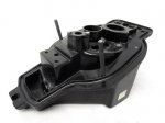
The pic below says it does, and provides alignment between the two.


Gimbal hsg.JPG
 

AShipShow

Lieutenant Commander
Joined
Jul 8, 2016
Messages
1,803
Well I'm back with frustration... I just finished a several day saga of pulling the engine, filling the old front mount holes, redrilling those holes in the correct location. I got the engine lowered back in today and I noticed the motor went on the front mounts much easier this time which gave me a sense of hope...

I also glued the fiber washers on to the transom plate and installed the double wound washers so I know they are there... I did an alignment pre-check and it felt pretty good, then tightened down the rear mounts evenly.
I started adjusting the front mounts up and down to get it centered vertically... To my dismay, I'm still getting heavy spline marks on the starboard side of the mount... :mad-new::mad-new::mad-new:

I have noticed that if I loosen the rear mounts, the alignment tool goes in really easy, so clearly the engine is capable of moving where it needs to be, but as soon as I retighten the rear mounts, back to heavy marks on the starboard side...
I've even tried tightening the rear mounts while the alignment tool was in..

I'm desperate here... any thoughts or suggestions?
 

Chris51280

Ensign
Joined
Jan 24, 2018
Messages
932
Good question. I forgot, what keeps the transom plate squared and aligned to the bearing and gimbal housing? I never paid attention when I did mine
 

AShipShow

Lieutenant Commander
Joined
Jul 8, 2016
Messages
1,803
Slight update...
I had my wife push the engine to the starboard side while I tightened the rear mounts... After doing that, the alignment bar just about fell into the coupler... so obviously I was super excited... however, when I went to put the drive on... made it until about an inch to go and no dice... Whats more important, even spline marks or the tool going in super easy?
Seems like I could chase my tail for hours and hours trying to get even marks... seems like I can check it 5 times in a row when its close and it shows different each time depending on how you insert the tool, remove the tool, look at it, talk about its mother...
 
Top