1994 Evinrude 50 HP Not Charging

Wreck'D Hunter

Recruit
Joined
Apr 17, 2021
Messages
5
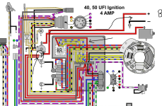
This "new-to-me engine" ran great all season but didn't charge the battery. Now time to troubleshoot it. Right away, I can see that the red wire from the rectifier is not connected to anything - see pic. The screw used to secure it to the black connection block is obviously not factory and there is no other wire behind it. This seems like the first place to start, at least to me.
Can someone offer direction on what wire needs to be connected to it, and where it comes from? I take it that it should go to the starter solenoid somehow... Thanks!IMG_8991.jpg
 

Crosbyman

Vice Admiral
Joined
Nov 5, 2006
Messages
5,899
usually stator yellows (2) feed the rectifier-regulator and the fat red RR output goes to the solenoid "B+ in post" from the battery so the charge current from the RR can return to the battery to charge it. got the wiring diagram ??

see example... does yout T&T work if u have T&T ???
1764170182677.png

see "example"
 

Attachments

  • 1764170001099.png
    1764170001099.png
    810.2 KB · Views: 3
Last edited:

Wreck'D Hunter

Recruit
Joined
Apr 17, 2021
Messages
5
usually stator yellows (2) feed the rectifier-regulator and the fat red RR output goes to the solenoid "B+ in post" from the battery so the charge current from the RR can return to the battery to charge it. got the wiring diagram ??

see example... does yout T&T work if u have T&T ???
View attachment 413391

see "example"
Ahhhh you are wise! It does have T&T and it does work. I just checked traced the red wire from the solenoid and it travels through a 20 amp fuse and goes to the terminal block, at the post just left of the thick red wire from the rectifier. From there it goes to the T&T wires. It would seem odd that the fix would be to simply move the thick red wire to the left so it connects to them all together. Before I move that wire over, I started the engine to check for DC voltage at the thick red wire coming out of the rectifier - the result - only 1.5V or so. So it would seem the stator or the rectifier... I did check the stator and the resistance readings seemed fine. Any thoughts on direction? Thank you.
 
Last edited:

Crosbyman

Vice Admiral
Joined
Nov 5, 2006
Messages
5,899
in regards to 1.5v on the red ............ measure the AC signal across the yellows from the STATOR
while running
btw some of those strips have small interconnect links to brigde over to the next bolt so check if you have one . or one missing

if you have just a rectifier (4 way bridge diodes) they are a dime a dozen on Amazon
 

Wreck'D Hunter

Recruit
Joined
Apr 17, 2021
Messages
5
in regards to 1.5v on the red ............ measure the AC signal across the yellows from the STATOR
while running
btw some of those strips have small interconnect links to brigde over to the next bolt so check if you have one . or one missing

if you have just a rectifier (4 way bridge diodes) they are a dime a dozen on Amazon
Test Complete - (relatively) steady 25 V AC across the 2 yellow leads (Wires 1&2 in the pic). For the test, I left them connected to the terminal block.
IMG_8991 2.jpg
 

Crosbyman

Vice Admiral
Joined
Nov 5, 2006
Messages
5,899
check RR part for OEM# .. 25VAC may turn out as a high DC if not regulated !!

check for proper grounding of RR........... and proper continuity between rr and strip post... red wire from RR looks frayed ???
 
Last edited:

Wreck'D Hunter

Recruit
Joined
Apr 17, 2021
Messages
5
check RR part for OEM# .. 25VAC may turn out as a high DC if only rectified !!

check for proper grounding of RR........... and proper continuity between rr and strip post... red wire from RR looks frayed ???
RR Part # 584476. Grounding appears to be solid. The red wire appears in good condition.
RR grounding wire travels from the base of the RR to the assembly mounting bold to the left.
Pic 1 shows the RR mount.

IMG_8994.jpg

Pic 2 shows the wire terminating on the left side of the RR, secured to the assembly.

IMG_8995.jpg
 

Crosbyman

Vice Admiral
Joined
Nov 5, 2006
Messages
5,899
carefully inspect crimps which sometimes lok OK but oxydize... measure ohms continuity to eliminate if all OK looks like the RR is defective if AC
up to you to change or not.

link output to battery via solenoid B+ post from the battery
 

Wreck'D Hunter

Recruit
Joined
Apr 17, 2021
Messages
5
carefully inspect crimps which sometimes lok OK but oxydize... measure ohms continuity to eliminate if all OK looks like the RR is defective if AC
up to you to change or not.

link output to battery via solenoid B+ post from the battery
Will do. Thank you for your time and insight today.
 
Top